
Lithium ion battery diaphragm, manufacturing method and application thereof

A lithium-ion battery and separator technology, applied in batteries, battery pack components, circuits, etc., can solve the problems of insufficient heat resistance of the separator and high risk of short-circuiting of lithium-ion batteries, and achieve good uniformity, reduced time, The effect of improving heat resistance

Pending Publication Date: 2020-02-21
JIANGSU ZENIO NEW ENERGY BATTERY TECH CO LTD
View PDF13 Cites 6 Cited by
  • Summary
  • Abstract
  • Description
  • Claims
  • Application Information

AI Technical Summary

Problems solved by technology

[0004] CN105070867A discloses a composite diaphragm, its preparation method and a lithium-ion battery, wherein the composite diaphragm includes a matrix diaphragm and a mixed coating coated on the surface of the matrix diaphragm; the material of the mixed coating includes ceramic particles, fluorine-containing Binder colloidal particles and water-soluble binder, the heat resistance of the separator described in this solution is insufficient, and the risk of short circuit in lithium-ion batteries is greater

Method used

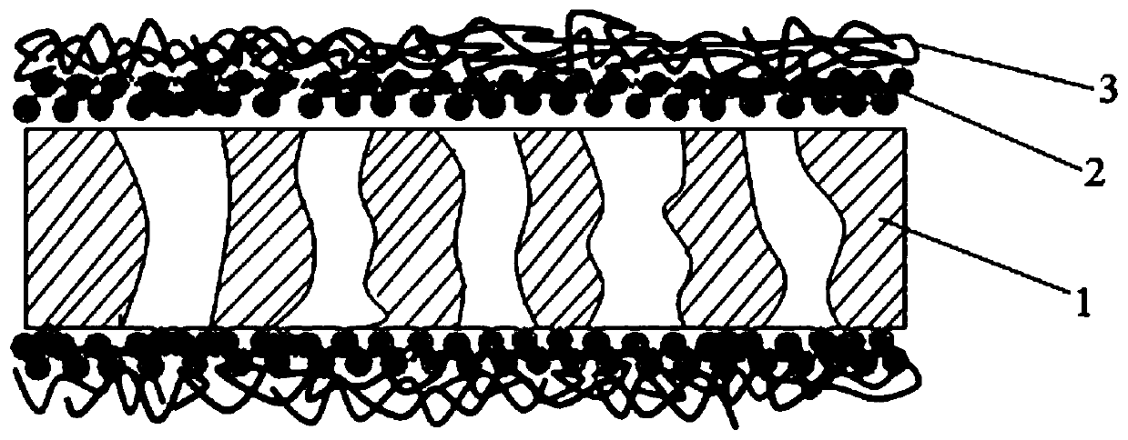

Image

  • Lithium ion battery diaphragm, manufacturing method and application thereof
  • Lithium ion battery diaphragm, manufacturing method and application thereof
  • Lithium ion battery diaphragm, manufacturing method and application thereof

Examples


Embodiment 1

[0099] The lithium-ion battery separator described in this example is recorded as 5P+2C+PE12+2C+5P; where PE12 represents the thickness of the polyethylene substrate is 12 μm, 2C represents the thickness of the ceramic coating layer on one side is 2 μm; 5P represents the thickness of the single-side The thickness of the surface water-based polyvinylidene fluoride layer is 5 μm;

[0100] Preparation method of lithium-ion battery diaphragm:

[0101] (1) Coating slurry containing nano-ceramic materials on both sides of a polyethylene substrate with a thickness of 12 μm to obtain a polymer substrate containing a ceramic coating layer, the thickness of the ceramic coating layer on one side is 2 μm;

[0102] The mass percentage of the nano-ceramic material in the slurry containing the nano-ceramic material is 40wt.%, the mass percentage of the water-based acrylic acid is 2wt.%, and the rest is water;

[0103] Wherein, the nano-ceramic material is alumina;

[0104] (2) Immerse the ...

Embodiment 2

[0119] The lithium-ion battery separator described in this embodiment is recorded as 5P+1.5C+PE9+1.5C+5P;

[0120] The difference between this embodiment and Example 1 is that the thickness of the polyethylene substrate in step (1) is 9 μm, the thickness of the ceramic coating layer on one side of the polyethylene substrate is 1.5 μm, and other conditions are the same as in Example 1. Compared to the exact same.

Embodiment 3

[0122] The lithium-ion battery separator described in this embodiment is recorded as 2P+1.5C+PP16+1.5C+2P;

[0123] The difference between this example and Example 1 is that the polyethylene substrate with a thickness of 12 μm is replaced with a polypropylene substrate with a thickness of 16 μm, and the thickness of the ceramic coating layer on one side of the polypropylene substrate is 1.5 μm. The thickness of the water-based polyvinylidene fluoride layer on one side surface is 2 μm; other conditions are exactly the same as those in Example 1.


PUM

PropertyMeasurementUnit
Thicknessaaaaaaaaaa
Particle sizeaaaaaaaaaa
Thicknessaaaaaaaaaa

Abstract

The invention relates to a lithium ion battery diaphragm, a manufacturing method and an application thereof. The lithium ion battery diaphragm comprises a polymer base material, a heat-resistant composite functional layer and a protective layer. The heat-resistant composite functional layer is located between the polymer base material and the protective layer, and the heat-resistant composite functional layer comprises a nano ceramic material and an aramid fiber polymer. The heat-resistant composite functional layer is excellent in heat resistance, and can prevent heat from being transferred to the polymer base material in a temperature rising process of the lithium ion battery so that a short circuit of the lithium ion battery caused by melting of the diaphragm is avoided, and safety performance of the lithium ion battery is improved.

Description

technical field [0001] The invention relates to the field of battery materials, in particular to a lithium-ion battery diaphragm, a preparation method and application thereof. Background technique [0002] As one of the four key materials of lithium-ion batteries, the diaphragm is not involved in the electrochemical reaction process, but it is a key inner layer component in lithium-ion batteries. Although the diaphragm does not directly affect key performances such as battery capacity, life, and charge-discharge rate, the "inertness" of the diaphragm is still the main factor to ensure the safety of lithium batteries. [0003] At present, the base materials of commercial lithium-ion battery separators are mainly polyolefin films. However, the performance requirements of lithium-ion batteries are getting higher and higher as the market demands. The transformation of the positive electrode material system, while bringing high capacity, also makes the material more prone to sid...

Claims


Application Information

Patent Timeline
IPC IPC(8): H01M2/16H01M2/14B82Y30/00
CPCB82Y30/00H01M2200/00H01M50/446H01M50/403Y02E60/10
Inventor 牛会琴江柯成
Owner JIANGSU ZENIO NEW ENERGY BATTERY TECH CO LTD
Learn More