Radar signal processor for perimeter defense

A signal processor and radar signal technology, applied in instruments, radio wave measurement systems, etc., can solve the problems of slow running speed, high noise of crystal oscillator chips, difficult signal detection, etc., achieve fast running speed, maintain consistent synchronization, and reduce noise Effect

Pending Publication Date: 2020-02-28
ANHUI SUN CREATE ELECTRONICS
View PDF0 Cites 0 Cited by
  • Summary
  • Abstract
  • Description
  • Claims
  • Application Information

AI Technical Summary

Problems solved by technology

[0003] 1. RF front-end faults are difficult to detect
[0004] The existing low-cost miniaturized signal processor transmits instructions to the RF front-end through the SPI interface to control the high-frequency signals required for the RF front-end to transmit. Unable to know, you need to use a spectrum analyzer to test whether the RF front-end has 24G high-frequency signal output, which is troublesome for the testing process
[0005] 2. Stationary targets cannot be detected
[0006] The existing low-cost miniaturized signal processor only has one-dimensional velocity resolution, and the distance is calculated by relying on the frequency difference and phase difference of different frequency signals. For stationary targets all at zero frequency, mixed with ground clutter, there is no suitable The method of removing clutter cannot effectively extract the stationary target information from the ground clutter. If the ground clutter is filtered out, the stationary target will also be filtered out, so it is difficult to detect the stationary target
[0007] 3. The noise caused by the crystal oscillator chip is too large
[0008] Due to the synchronization of the radar machine, the clock of the RF front-end is drawn from the crystal oscillator chip in the signal processor through the internal bus, which can ensure the synchronization of the entire system. Interference, the starting point of the radar is interfered, when the signal is transmitted to the signal processor, the noise will become larger, it is difficult to detect the target with low intensity or the weak signal at a long distance
[0009] 4. Long running time
The main frequency of the original signal processor is 150M, and the main frequency of the current signal processor is 200M, and the running speed is 30% slower than the current one.

Method used


Image

  • Radar signal processor for perimeter defense

Examples


Embodiment Construction

[0044] The following will clearly and completely describe the technical solutions in the embodiments of the present invention with reference to the accompanying drawings in the embodiments of the present invention. Obviously, the described embodiments are only some, not all, embodiments of the present invention. Based on the embodiments of the present invention, all other embodiments obtained by persons of ordinary skill in the art without making creative efforts belong to the protection scope of the present invention.

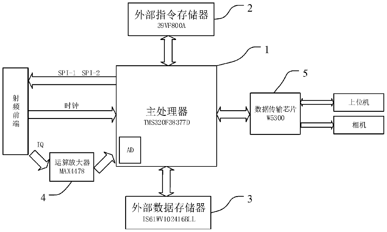
[0045] Depend on figure 1 As shown, a radar signal processor for perimeter defense of the present invention includes:

[0046] Main processor 1, said main processor 1 is a DSP signal processor, that is, a DSP chip. The DSP signal processor has a built-in AD module, the model is TMS320F28377D, and the manufacturer is Texas Instruments.

[0047] External command memory 2, the external command memory 2 is a FLASH storage chip for storing radar configuration para...


PUM


Abstract

The invention discloses a radar signal processor for perimeter defense. The radar signal processor comprises a main processor, an external instruction memory, an external data memory, an operational amplifier and a data transmission chip, and the external instruction memory, the external data memory, the operational amplifier and the data transmission chip are each connected with the main processor. According to the invention, the radar signal processor employs two-dimensional FFT processing, and the main processor has dual cores and is high in operation efficiency, so the fault detection function on the radio frequency front end is added, and a clock of the signal processor is provided by the radio frequency front end.

Description

technical field [0001] The invention relates to the technical field of radar signal processing, in particular to a radar signal processor for perimeter defense. Background technique [0002] Radar signal processing is the core part of the radar system. Its main functions are: to provide timing for the whole machine, control the waveform required for the RF front-end transmission; sample the radar echo signal, and output the processing result to the host computer. In the existing low-cost miniaturized radar signal processor, there are mainly the following defects: [0003] 1. RF front-end faults are difficult to detect [0004] The existing low-cost miniaturized signal processor transmits instructions to the RF front-end through the SPI interface to control the high-frequency signals required for the RF front-end to transmit. It is impossible to know, and it is necessary to use a spectrum analyzer to test whether the RF front-end has 24G high-frequency signal output, which ...

Claims


Application Information

Patent Timeline
IPC IPC(8): G01S7/02
CPCG01S7/02
Inventor 张阳路同亚黄涛吴俊段登李朋秦胜贤王为
Owner ANHUI SUN CREATE ELECTRONICS
Why Eureka
Try Eureka