Plasma torch molten metal wire consumable material deposition extrusion 3D printing nozzle

A plasma torch and molten metal technology, applied in the field of metal 3D printing nozzles, can solve problems such as difficult effective combination, complicated operation and maintenance, and large heat loss

Inactive Publication Date: 2020-03-06
蒋锐
View PDF7 Cites 2 Cited by
  • Summary
  • Abstract
  • Description
  • Claims
  • Application Information

AI Technical Summary

Problems solved by technology

The above reasons lead to expensive metal 3D printing equipment, complicated operation and maintenance, which is not conducive to the promotion of 3D printing technology, so it is urgent to develop a low-cost, high-efficiency metal 3D printing equipment
[0005] The 3D printing method based on the FDM principle melts the metal wire consumables in the nozzle, and the nozzle moves along the section profile of the part and the filling trajectory, and at the same time extrudes the molten material, the material solidifies rapidly, and is combined with the surrounding material or the material of the previous layer Coagulation, the material is formed by layer-by-layer printing. This processing method can greatly reduce the cost of metal 3D printing and improve the forming efficiency. Extrusion jet is the core component of the printer. Currently, the 3D printer based on FDM Most of them use resistance wire and electromagnetic induction heating, but the problems of resistance wire heating are: 1. The heating method of resistance wire has low heating efficiency, large heat loss and high energy consumption; 2. The heating capacity of resistance wire heating

Method used


Image

  • Plasma torch molten metal wire consumable material deposition extrusion 3D printing nozzle
  • Plasma torch molten metal wire consumable material deposition extrusion 3D printing nozzle

Examples


Embodiment Construction

[0013] The present invention is described in further detail below in conjunction with specific embodiment:

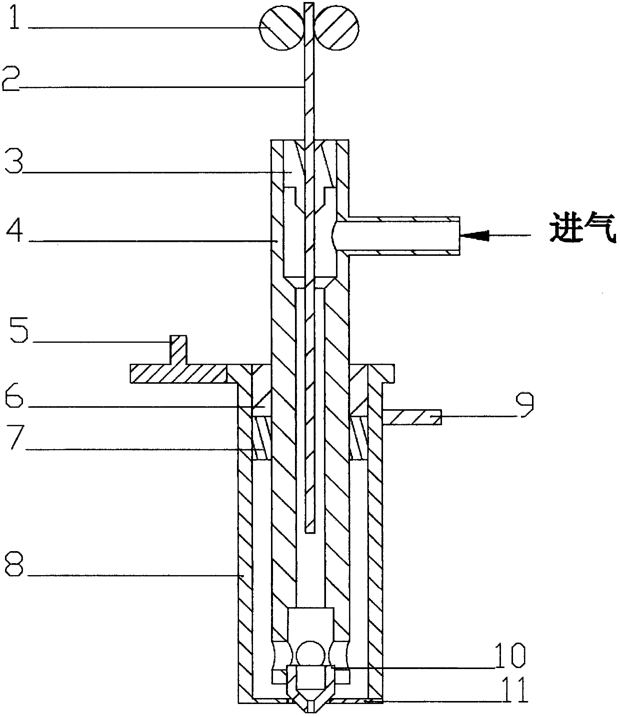
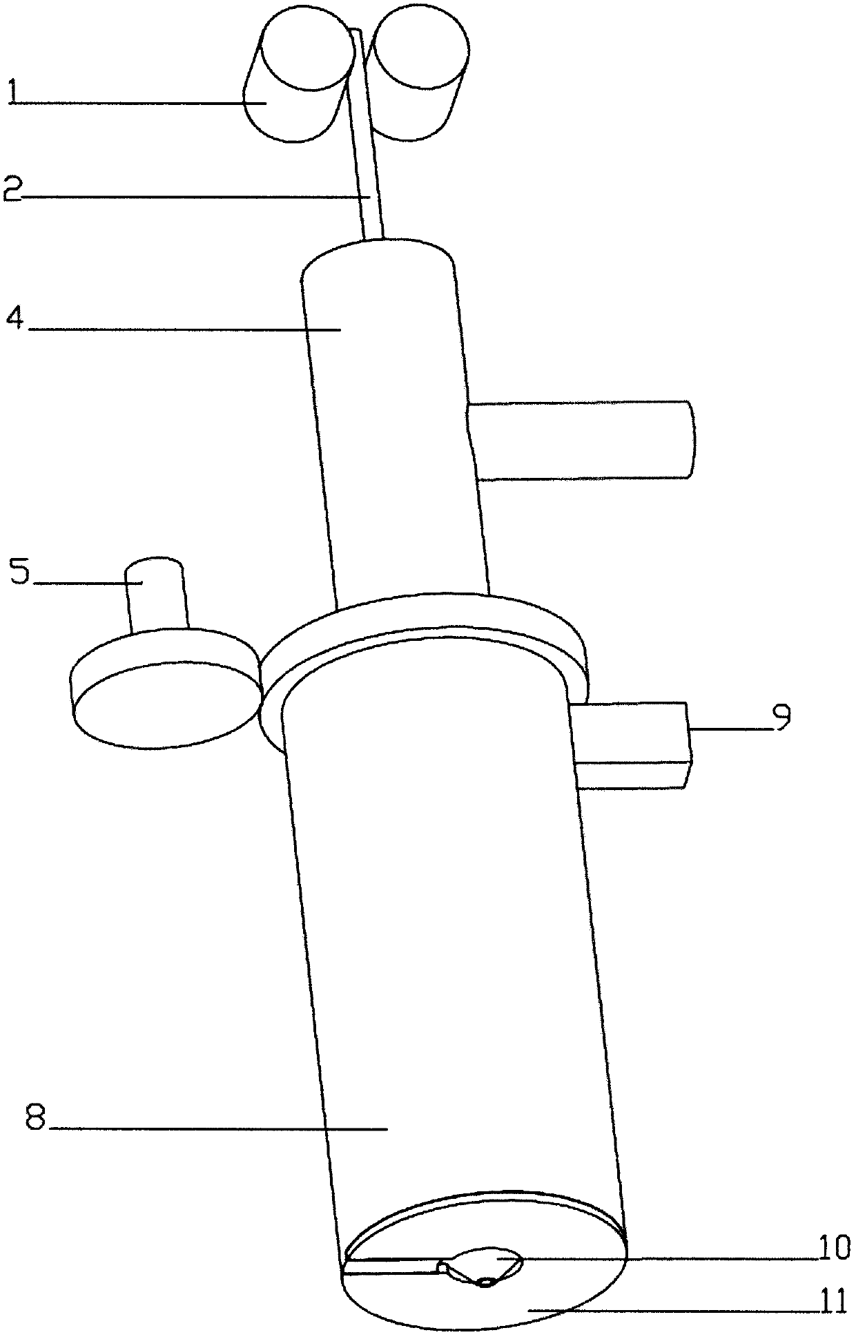
[0014] Such as figure 1 , 2 As shown, the feeding device 1 is driven by a control motor to feed the rollers, and is fixed on a fixed seat that can move on the X and Y axes.

[0015] The cathode feeding tube 4 is fixed on a fixed seat that can move on the X and Y axes.

[0016] The seal 3 is located between the cathode feed tube 4 and the wire consumable 2, and has high temperature resistant sealing properties to prevent gas leakage.

[0017] The sealing member 7 is located between the bearing 6, the anode 8, and the cathode feed pipe 4, and has high-temperature-resistant sealing properties to prevent gas leakage.

[0018] The shower head 10 is made of a metal material with low electron escape power and high temperature resistance, and is connected with the cathode feed pipe 4 .

[0019] The high-temperature insulating ring 11 is high-temperature-resistant and has go...


PUM


Abstract

The invention relates to a plasma torch molten metal wire consumable material deposition extrusion 3D printing nozzle. The 3D printing nozzle comprises a feeding device, a plasma torch direction adjusting device, an anode, a cathode feeding pipe, a sealing member, a carbon brush, a bearing and a nozzle body. According to the 3D printing nozzle, a cooled and solidified layer is rapidly heated to anear-melting state through a plasma torch before molten printing material is extruded, so that the defect that the bonding is not firm due to the excessive temperature difference between the printed layer and the extruded material is eliminated, and a compact solid is formed. Inert gas flows out of a hole in the joint between the cathode feeding pipe and the upper end of the nozzle body, the gas can cool the upper end of the consumable material, and the outlet is kept in a molten state, so that the problem that the metal wire consumable material is softened and can not be extruded due to the fact that heat transfer of molten liquid metal is too fast is solved, the defects that the printing nozzle is complex in structure and needs a special cooling system are overcome, the printing precision is improved, more energy is saved, and the requirement on the material is reduced.

Description

technical field [0001] The invention relates to a metal 3D printing nozzle, in particular to a 3D printing nozzle that uses a plasma torch to melt metal wire consumables for deposition and extrusion. Background technique [0002] 3D printing, also known as three-dimensional printing, is a new technology that uses laser beams, electron beams, electric arcs and other heat sources to scan and melt metal powder layer by layer and quickly solidify them to form three-dimensional objects based on three-dimensional mathematical models of components. This technology can almost Make models of any shape, no longer limited by traditional manufacturing methods, this technology can be used in jewelry, footwear, industrial design, automotive, aerospace, medical and many other fields. [0003] At present, relatively mature metal 3D printing technologies include selective laser sintering technology, direct metal powder laser sintering technology, selective laser melting technology, laser nea...

Claims


Application Information

Patent Timeline
IPC IPC(8): B22F3/115B33Y30/00
CPCB22F3/115B22F3/003B33Y30/00
Inventor 蒋锐
Owner 蒋锐
Why Eureka
Try Eureka