
Efficient spray full-coverage rotational flow spray desulfurization tower and desulfurization system

A desulfurization system and full-coverage technology, applied in the field of flue gas desulfurization treatment, can solve problems such as unbalanced equipment development, affecting the economic and environmental benefits of enterprises, and unstable operation, so as to improve the desulfurization treatment effect, prolong the full contact time, Good defogging effect

Inactive Publication Date: 2020-03-13
WAFANGDIAN YONGNING FIRE GRATE MFG
View PDF6 Cites 0 Cited by
  • Summary
  • Abstract
  • Description
  • Claims
  • Application Information

AI Technical Summary

Problems solved by technology

[0003] At present, the development of major domestic desulfurization and dust removal equipment is uneven and uneven. Some equipment is crudely manufactured, resulting in unstable operation, low efficiency, and short service life, which directly affects the economic and environmental benefits of enterprises.

Method used


Image

  • Efficient spray full-coverage rotational flow spray desulfurization tower and desulfurization system
  • Efficient spray full-coverage rotational flow spray desulfurization tower and desulfurization system
  • Efficient spray full-coverage rotational flow spray desulfurization tower and desulfurization system

Examples


Embodiment 1

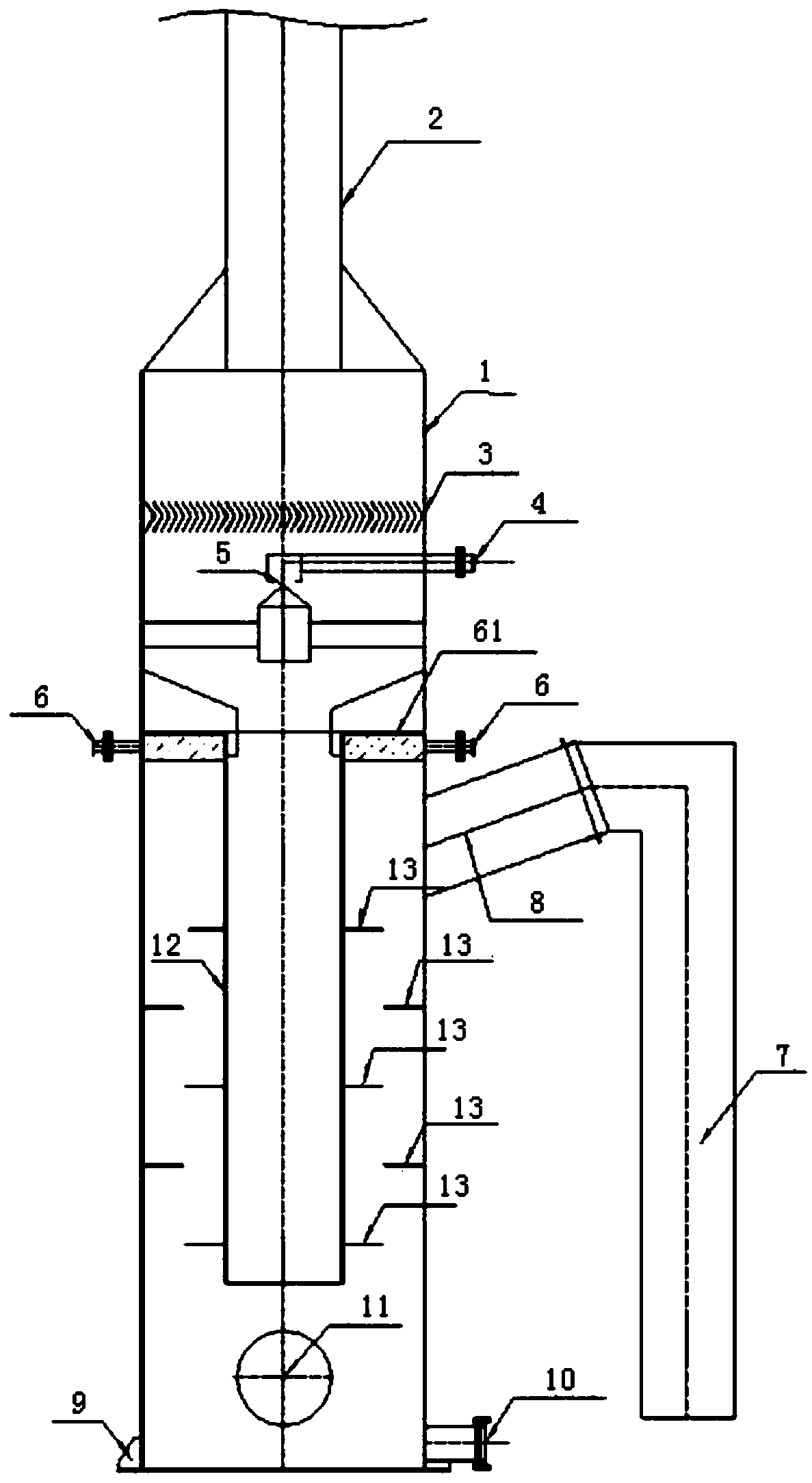
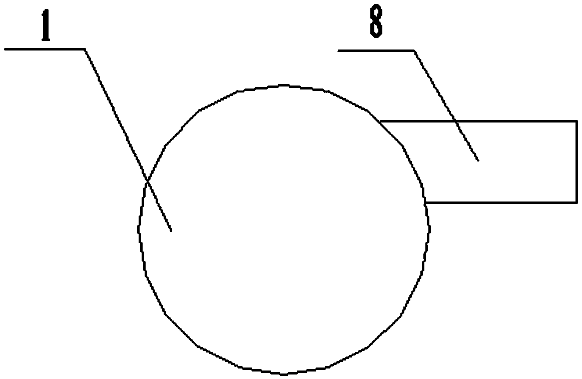
[0023] A high-efficiency spray full-coverage swirl spray desulfurization tower, including: tower body 1, first liquid inlet 4, first liquid distributor 5, second liquid inlet 6, second liquid distributor 61, flue gas inlet 8. Bile duct 12, baffle plate 13, base 9, return water outlet 10, flue gas outlet 2, demister 3;

[0024] The tower body 1 and the bile duct 12 are cylindrical structures; the bile duct 12 is inside the tower body 1 and coaxial with the tower body 1; the bile duct 12 is not in contact with the bottom of the tower body 1; The baffles 13 are annular, interlaced and fixed between the tower body 1 and the bile duct 12;

[0025] The first water inlet 4 and the first liquid distributor 5 are installed above the bile duct 12; the second liquid inlet 6 and the second liquid distributor 61 are arranged in a circular shape between the tower body 1 and the bile duct 12 above the space;

[0026] The flue gas inlet 8 is installed on the side of the tower body 1, below ...

Embodiment 2

[0036] The difference from Embodiment 1 is that the flue gas inlet 8 is arranged eccentrically relative to the tower body 1 . This makes the flue gas generate swirling flow in the tower body 1, further improving the desulfurization effect of the flue gas.

Embodiment 3

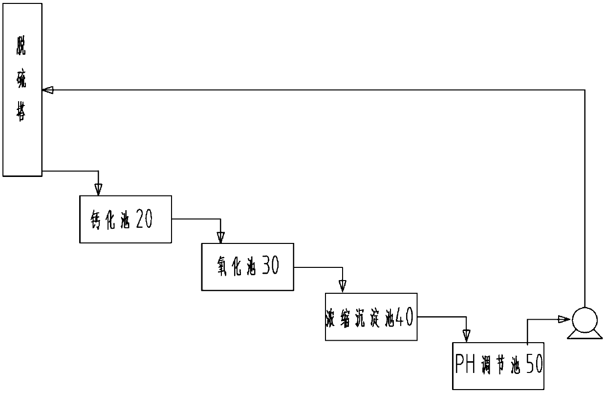
[0038] A desulfurization system, comprising the high-efficiency spray full-coverage swirl spray desulfurization tower in claims 1-9, the calcification pool 20, the oxidation pool 30, the concentrated sedimentation pool 40, and the pH adjustment pool 50; the high-efficiency spray full-coverage swirl The treatment liquid in the flow spray desulfurization tower flows through the return water outlet 10, the calcification tank 20, the oxidation tank 30, the concentration sedimentation tank 40, and the pH adjustment tank 50 in sequence, and then is pumped to the first liquid inlet 4 and the second inlet Liquid port 6.

[0039] The oxidation pond 30 includes an air aeration system.

[0040] The treatment liquid used in the system is sodium hydroxide solution, which absorbs sulfur dioxide in the desulfurization tower to generate sodium sulfite and sodium bisulfite. Afterwards, the treatment liquid containing sodium sulfite and sodium bisulfite enters the calcification tank 20 through...


PUM


Abstract

Based on the defects in the prior art, the invention provides an efficient spray full-coverage rotational flow spray desulfurization tower with characteristics of stable desulfurization process operation, high efficiency and simple operation, and a desulfurization system. The efficient spray full-coverage rotational flow spray desulfurization tower comprises a tower body, a first liquid inlet, a first liquid distributor, a second liquid inlet, a second liquid distributor, a flue gas inlet, a liner pipe, flow baffle plates, a base, a water return outlet, a flue gas outlet and a demister, wherein the tower body and the liner pipe have cylindrical structures, the liner pipe is arranged in the tower body and is coaxial with the tower body, the liner pipe does not contact the bottom of the tower body, and the flow baffle plates are annular and are fixed between the tower body and the liner pipe in a staggered manner. The invention further discloses a desulfurization system, which comprisesa desulfurization tower, a calcification tank, an oxidation tank, a concentration sedimentation tank and a PH regulating tank. According to the invention, flue gas is subjected to repeated flow baffling in the tower through the flow baffle plates, so that the full contact time of the flue gas and the treatment liquid is prolonged, and the desulfurization treatment effect is improved.

Description

technical field [0001] The invention relates to the field of flue gas desulfurization treatment, in particular to a high-efficiency spray full-coverage swirl spray desulfurization tower and a desulfurization system. Background technique [0002] The atmosphere is one of the most basic environmental elements for the survival of human beings and all things on the earth. Atmospheric environment pollution will bring disasters to human survival, life, work, and sustainable development. Therefore, practical technologies and equipment for controlling atmospheric environmental pollution are particularly important. Today's scientific and technological innovation, environmental progress and the improvement of human life quality, environmental quality is getting more and more attention, and the pollutant discharge standards are getting higher and higher. my country's environmental standards are in line with the emission standards of advanced countries in the world, and the technologic...

Claims


Application Information

Patent Timeline
Patent Type & Authority Applications(China)
IPC IPC(8): B01D53/50B01D53/78B01D53/96B01D50/00
CPCB01D53/504B01D53/502B01D53/78B01D53/96B01D2251/304B01D2251/604B01D2258/0283B01D50/40
Inventor 王聪会王丹王选君邹年宏韩艳慧万鑫悦
Owner WAFANGDIAN YONGNING FIRE GRATE MFG
Learn More