Composite cooling water disc and manufacturing method and application thereof

A cooling water, composite technology, used in semiconductor/solid-state device manufacturing, electrical components, circuits, etc., can solve problems such as the heat transfer coefficient of the device is not improved, copper cannot be exposed, copper ions leak, etc., to promote thermal isostatic Pressure welding effect, high industrial application value, effect of preventing copper leakage

Active Publication Date: 2020-03-24
宁波江丰芯创科技有限公司
View PDF14 Cites 4 Cited by
  • Summary
  • Abstract
  • Description
  • Claims
  • Application Information

AI Technical Summary

Problems solved by technology

[0003] CN109817544A discloses a semiconductor equipment heating and cooling composite tray device, which improves the processing and cooling efficiency of wafers by reducing the transfer path of wafers between the heating zone and the cooling zone, but the structure of the device is complex, and the cooling zone The heat transfer coefficient is still high
[0004] CN202205717U discloses a wafer cooling device, which blows gas to the wafer through an additional gas injection element, which not only avoids residual moisture on the surface of the wafer after cooling, but also reduces the cooling time of the wafer and improves the wafer cooling performance. Cooling efficiency, but the heat transfer coefficient of the gas injection method is still low, and the energy consumption is high
[0005] CN208738190U discloses a kind of wafer cooling chamber, by adopting a plurality of driving devices to transport wafers to the cooling chamber respectively, thereby avoiding the problem of uneven heat dissipation between wafers, but the heat transfer coefficient of the device does not improve
[0006] To sum up, at present, people have not thought of improving the cooling efficiency by improving the material of the cooling water plate. This is because the material for making the cooling plate is generally aluminum alloy. If the cooling device in semiconductor equipment is generally made of copper, although the thermal conductivity of copper The coefficient is 1.5 times that of aluminum, and the cooling capacity will be greatly improved. However, in semiconductor equipment, copper cannot be exposed outside, otherwise copper ions will leak and the wafer will be scrapped.
[0007] Therefore, it is necessary to develop a cooling water tray with a high heat transfer coefficient and a manufacturing method thereof, so that copper ion leakage does not occur while solving the problem of low heat transfer coefficient of the cooling water tray

Method used


Image

  • Composite cooling water disc and manufacturing method and application thereof
  • Composite cooling water disc and manufacturing method and application thereof
  • Composite cooling water disc and manufacturing method and application thereof

Examples


Embodiment 1

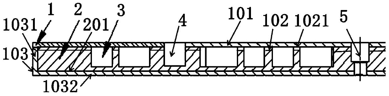
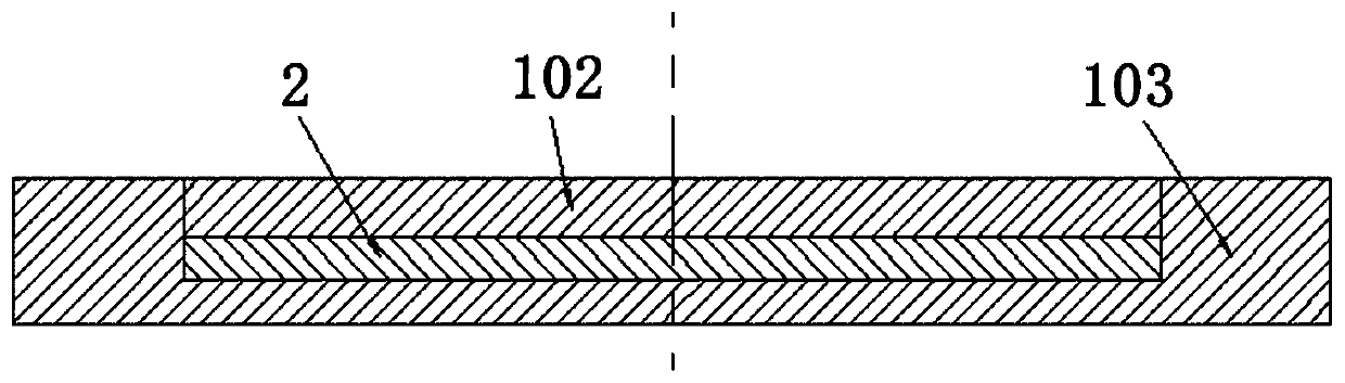
[0125] This embodiment provides a composite cooling water tray, such as figure 2 As shown, the cooling water tray includes an aluminum shell 1 and a copper layer 2 wrapped in the aluminum shell 1;

[0126] The aluminum shell includes an aluminum upper layer 101, an aluminum middle layer 102 and a grooved aluminum base 103; a copper layer 2 and the aluminum middle layer 102 are sequentially arranged on the grooved part of the grooved aluminum base 103 from bottom to top, The upper surface 1021 of the aluminum intermediate layer 102 is flush with the protruding surface 1031 of the grooved aluminum base 103, the thickness of the groove portion 1032 of the grooved aluminum base 103 is 1mm, the thickness of the aluminum upper layer 101 is 1mm, and the copper layer The thickness of 2 is 5 mm, the thickness of aluminum middle layer 102 is 1 mm, the material of aluminum upper layer 101, aluminum middle layer 102 and grooved aluminum base 103 is aluminum alloy 6061, and the material o...

Embodiment 2

[0138] This embodiment provides a composite cooling water tray, the cooling water tray includes an aluminum shell and a copper layer wrapped in the aluminum shell;

[0139] The aluminum shell includes an aluminum upper layer, an aluminum middle layer, and a grooved aluminum base; a copper layer and the aluminum middle layer are sequentially arranged in the groove of the grooved aluminum base from bottom to top, and the upper surface of the aluminum middle layer It is flush with the protruding surface of the grooved aluminum base, the thickness of the groove part of the grooved aluminum base is 1.5mm, the thickness of the upper aluminum layer is 1.5mm, the thickness of the copper layer is 4.5mm, and the thickness of the aluminum middle layer 0.5mm, the aluminum upper layer, the aluminum middle layer and the grooved aluminum base are made of aluminum alloy 6063, and the copper layer is made of TU2 oxygen-free copper;

[0140]The aluminum intermediate layer and the copper layer a...

Embodiment 3

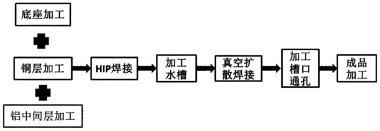
[0151] This embodiment provides a composite cooling water tray, the cooling water tray has the same structure as that of Embodiment 1, and its manufacturing method includes the following steps:

[0152] (1) After punching a through hole on the copper layer, carry out physical vapor deposition coating on the surface of the copper layer. The film thickness is 9 μm, and the film composition is titanium with a purity of 99.95%. Aluminum pins are driven into the through holes, and the aluminum pins are The unilateral fit gap between the sub and the through hole is 0.025mm;

[0153] (2) Ultrasonic cleaning of the copper layer, grooved aluminum base and aluminum interlayer for 8 minutes, followed by vacuum drying to complete the pretreatment;

[0154] (3) A copper layer and an aluminum intermediate layer are arranged sequentially from bottom to top in the groove portion of the groove-shaped aluminum base to obtain assembled components, and the assembled components are sequentially su...


PUM

PropertyMeasurementUnit
depthaaaaaaaaaa
widthaaaaaaaaaa
widthaaaaaaaaaa

Abstract

The invention provides a composite cooling water disc. The problem that an existing cooling water disc is low in heat transfer coefficient is solved by arranging the aluminum shell and the copper layer wrapped in the aluminum shell, copper is completely wrapped in the aluminum shell, it can be guaranteed that copper metal cannot leak out. The composite cooling water disc is applied to the field ofsemiconductors, and the stability of chip manufacturing can be guaranteed. The invention further provides a manufacturing method of the cooling water disc. Firstly, a copper layer is welded in an aluminum shell through hot isostatic pressing to obtain a welded assembly. After the assembly is machined out of the water tank, the assembly and the upper aluminum layer are combined and subjected to vacuum diffusion welding to obtain the cooling water disc, the copper layer is completely wrapped in the aluminum shell, the water tank cannot be blocked, and the manufactured cooling water disc is highin cooling efficiency and has high industrial application value.

Description

technical field [0001] The invention relates to the technical field of semiconductor equipment, in particular to a composite cooling water pan and a manufacturing method and application thereof. Background technique [0002] In the semiconductor chip manufacturing process, temperature control is a very important task. Temperature not only plays an important role in the process of wafer production, but also "plays waste heat" on the performance of devices on the wafer after the related process is completed. For example, for a wafer that has just been removed from a high-temperature process chamber such as a dry etching chamber, a vapor deposition chamber, or a furnace chamber, due to the different device densities distributed on the wafer, the temperature at various places on the surface of the wafer appears to be different. If the temperature difference is not resolved in time and the wafer is naturally exposed to the atmospheric environment, the surface of the wafer may ca...

Claims


Application Information

Patent Timeline
Patent Type & Authority Applications(China)
IPC IPC(8): H01L21/67B23P15/00
CPCH01L21/67109B23P15/00
Inventor 姚力军潘杰边逸军王学泽占卫君
Owner 宁波江丰芯创科技有限公司
Why Eureka
Try Eureka