
Multi-core few-mode microstructure optical fiber for field of space division-mode division multiplexing

A micro-structured optical fiber, mode division multiplexing technology, applied in cladding optical fiber, light guide, optical, etc., can solve the problems of limited signal-to-noise ratio, limited maximum frequency efficiency, capacity compression, etc., to ensure transmission capacity and control size , the effect of reducing the size

Active Publication Date: 2020-03-27
NORTHEASTERN UNIV
View PDF4 Cites 15 Cited by
  • Summary
  • Abstract
  • Description
  • Claims
  • Application Information

AI Technical Summary

Problems solved by technology

[0003] Among the five dimensions in which optical signals can be modulated or multiplexed, time and frequency (wavelength) multiplexing have been used in the early stages of optical fiber communication development. At present, there is not much potential to be tapped. Relying on polarization multiplexing can only improve one level. For the complex amplitude dimension, limited by the signal-to-noise ratio of the optical fiber communication system, the modulation order cannot be increased without limit, resulting in a limited maximum frequency efficiency. Only space is a dimension that has not yet been fully developed and utilized, and can enable Under the framework, the capacity of optical fiber communication has been rapidly increased by 2-3 orders of magnitude to solve the foreseeable capacity shrinkage problem in the future. As the bottleneck of traditional single-mode optical fiber transmission capacity becomes increasingly prominent, space division / mode division multiplexing technology has gradually received attention and has become the current Eye-catching cutting-edge research directions and hot topics in the field of optical fiber communication

Method used


Image

  • Multi-core few-mode microstructure optical fiber for field of space division-mode division multiplexing
  • Multi-core few-mode microstructure optical fiber for field of space division-mode division multiplexing
  • Multi-core few-mode microstructure optical fiber for field of space division-mode division multiplexing

Examples


Embodiment 1

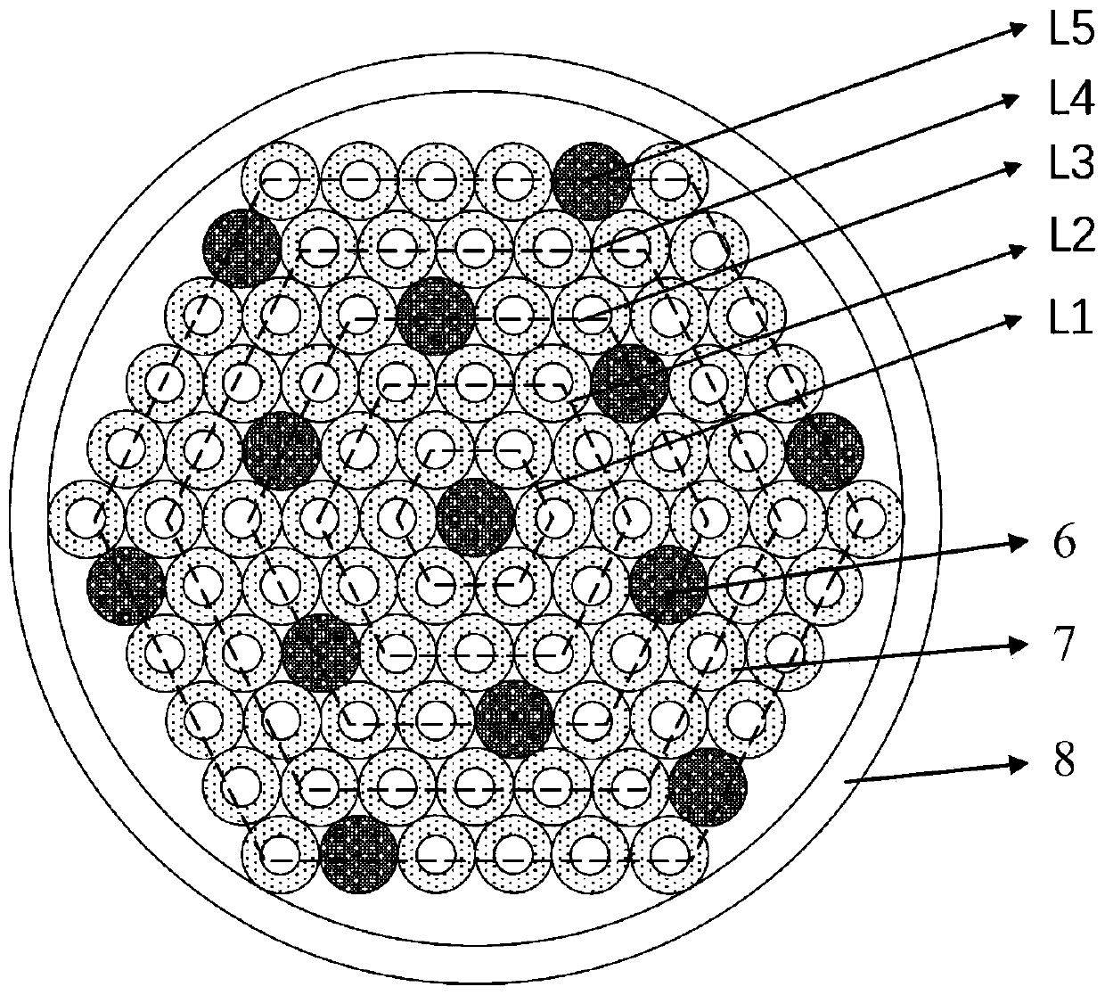
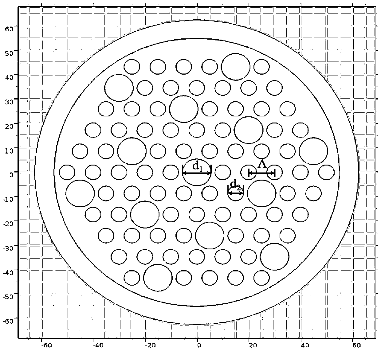
[0030] This embodiment provides a multi-core few-mode microstructured optical fiber used in the field of space division-mode division multiplexing. It is designed with 13 few-mode fiber cores and is a 13-core multi-core few-mode microstructured optical fiber. Its structure diagram is as follows figure 1 and figure 2 As shown, the multi-core few-mode microstructure optical fiber used in the space division-mode division multiplexing field of the present embodiment includes a central region and an outer cladding region, and the outer periphery of the central region is provided with an outer cladding region; the central region is composed of 13 few-mode fibers Core and air hole inner cladding, few-mode core diameter d 1 is 10μm, the inner cladding diameter of the air hole is 10μm, and the diameter of the air hole is d 2 is 6μm, the center of the inner cladding of two adjacent air holes, the interval Λ is 10μm.

[0031] The outer cladding is made of quartz material with a refrac...

Embodiment 2

[0034] A multi-core few-mode microstructure optical fiber used in the field of space division-mode division multiplexing, the structure is the same as that of embodiment 1, and the difference from embodiment 1 is that the 13 few-mode cores are made of quartz material, and the air hole inner cladding The area and the outer cladding area are made of fluorine-doped quartz material. The main function of fluorine is to reduce the refractive index of quartz, to ensure that the refractive index of the air hole inner cladding area and the outer cladding area is lower than that of the few-mode fiber core, and to ensure that the light is confined in the fiber core area. transmission.

Embodiment 3

[0036] A multi-core few-mode microstructured optical fiber used in the field of space division-mode division multiplexing in this embodiment, its structural schematic diagram is as follows Figure 4 As shown, the difference from Embodiment 1 and 2 is that the multi-core few-mode microstructure optical fiber used in the field of space division-mode division multiplexing is a six-layer air hole structure, and 36 air holes are added in the outermost layer , which effectively isolates the contact between the few-mode fiber core set on the fifth layer and the outer sleeve. The few-mode fiber core is a 10 μm high refractive index material, and the air hole inner cladding area and outer cladding area are less mode core refractive index 0.1%-1% low refractive index material, the air hole diameter is 6μm, and the pitch is 10μm.


PUM

PropertyMeasurementUnit
Diameteraaaaaaaaaa
Diameteraaaaaaaaaa
Sizeaaaaaaaaaa

Abstract

A multi-core few-mode microstructure optical fiber for the field of space division-mode division multiplexing comprises a central area and an outer cladding area, and the outer cladding area is arranged on the periphery of the central area. The central area comprises few-mode fiber cores and an air hole inner cladding, and a plurality of few-mode fiber cores are arranged in the central area. The number of degenerate transmission modes of a single few-mode fiber core is greater than or equal to 2. One few-mode fiber core is arranged in the center of the central area, the other few-mode fiber cores are uniformly distributed around the few-mode fiber core in the center, any three adjacent few-mode fiber cores are equidistant, and an air hole inner cladding is arranged between the periphery ofeach few-mode fiber core and the two adjacent few-mode fiber cores. According to the optical fiber, the number of degenerate transmission modes of each fiber core can be ensured to be more than two by designing and adjusting the diameters of the air holes and the distances between the holes and controlling the refractive index difference of materials, the size of the optical fiber is reduced as much as possible, inter-core / inter-mode crosstalk and differential mode group delay are controlled on the basis to meet the communication requirement, and the communication capacity is improved.

Description

technical field [0001] The invention belongs to the technical field of optical fiber communication, and in particular relates to a multi-core few-mode microstructure optical fiber used in the field of space division-mode division multiplexing. Background technique [0002] As one of the most important information transmission methods, optical fiber communication has laid the foundation stone for today's information society. After nearly half a century of development, the single-mode optical fiber communication system has gradually reached the Shannon limit of its transmission capacity. However, the demand for future communication capacity will continue to grow at a rate of 100 times every ten years, and fiber optic communication technology is facing severe challenges. There are five physical dimensions of optical signals that can be modulated or multiplexed, namely time, frequency (wavelength), polarization state, complex amplitude and space. Compared with other dimensions,...

Claims


Application Information

Patent Timeline
IPC IPC(8): G02B6/02
CPCG02B6/02314G02B6/02338
Inventor 程同蕾张帆李曙光闫欣张学楠
Owner NORTHEASTERN UNIV
Learn More