
Ceramic shell, method for processing surface thereof, and electronic equipment

A technology for ceramic shells and processing methods, which is applied in the field of ceramic processing and can solve problems such as surface processing of ceramic shells that needs to be further studied

Inactive Publication Date: 2020-04-17
GUANGDONG OPPO MOBILE TELECOMM CORP LTD
View PDF6 Cites 12 Cited by
  • Summary
  • Abstract
  • Description
  • Claims
  • Application Information

AI Technical Summary

Problems solved by technology

[0003] Therefore, the processing of the surface of the ceramic shell needs to be further studied

Method used


Image

  • Ceramic shell, method for processing surface thereof, and electronic equipment
  • Ceramic shell, method for processing surface thereof, and electronic equipment
  • Ceramic shell, method for processing surface thereof, and electronic equipment

Examples


preparation example Construction

[0017] Preparation of ceramic blanks: mixing ceramic raw material powders and binders, and then adopting injection molding, tape casting or dry pressing to obtain ceramic green blanks. Among them, according to the type of ceramics, at least one of alumina powder, zirconia powder and zirconium nitride powder can be used, and the purity of the ceramic raw material powder is above 99.99%; the binder can use paraffin wax, polyethylene glycol, stearic acid , one or more of dioctyl phthalate, polyethylene, polypropylene, polymethyl methacrylate, and polyoxymethylene. Based on the total weight of the above-mentioned ceramic raw material powder and binder, the content of the ceramic raw material powder is 70wt% to 99wt%, and the content of the binder is 1wt% to 30wt%. The specific content value can be determined according to the selected ceramic molding process. allow.

[0018] Degumming: put the ceramic blank in the degumming box for degumming or degreasing, the degumming temperatur...

Embodiment 1

[0040] The steps of ceramic shell preparation and surface processing are the same as in Example 1, the difference is that when laser engraving texture patterns, the processing power of the carbon dioxide laser is 3W, and the processing rate of the carbon dioxide laser is 0.2mm / s.

[0041] The textured pattern on the outer surface of the processed ceramic shell has a depth of 0.005 mm, and the ceramic shell has no cracks during processing, and the color of the ceramic surface is uniform.

Embodiment 2

[0043] The steps of preparation and surface processing of the ceramic shell are the same as those in Embodiment 1, the difference being that the processing power of the carbon dioxide laser is 8W and the processing rate of the carbon dioxide laser is 1.0mm / s when the laser is engraving the texture pattern.

[0044] The textured pattern on the outer surface of the processed ceramic shell has a depth of 0.01 mm, and the ceramic shell has no cracks during processing, and the color of the ceramic surface is uniform.


PUM

PropertyMeasurementUnit
Depthaaaaaaaaaa
Spot diameteraaaaaaaaaa
Line widthaaaaaaaaaa

Abstract

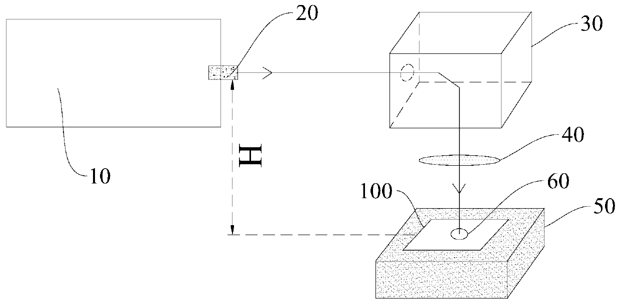
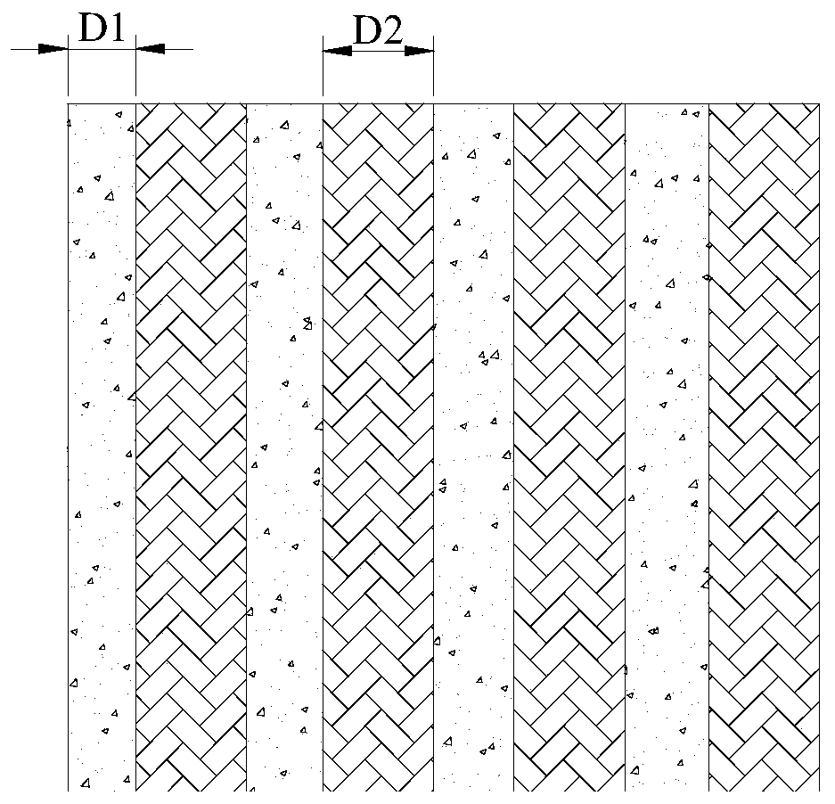
The invention provides a ceramic shell, a method for processing the surface thereof, and electronic equipment. The method comprises the steps: performing laser etching on the outer surface of the ceramic shell through a carbon dioxide laser to form a texture pattern, wherein the depth of the texture pattern is 0.005-0.09 mm. Therefore, not only can the three-dimensional texture be processed on thesurface of the ceramic shell, but also the ceramic surface (high gloss, bright surface) of the part which is not subjected to laser etching and the ceramic surface (relatively low gloss, matte surface) of the part which is subjected to laser etching form a surface appearance effect with alternate brightness and darkness or matte contrast, so the appearance effect of the surface of the ceramic shell is enriched; furthermore, due to the fact that the depth of the machined texture pattern is small, the ceramic shell with the small thickness can be prevented from being broken in the machining process, the surface machining yield of the ceramic shell can be improved, and it is effectively guaranteed that the obtained ceramic shell still has good mechanical strength such as falling resistance and impact resistance.

Description

technical field [0001] The present application relates to the technical field of ceramic processing, and in particular, relates to a processing method for a ceramic shell and its surface, and electronic equipment. Background technique [0002] Ceramics have properties such as high strength, high gloss, high fracture toughness, excellent heat insulation performance, and high temperature resistance. As mobile phone structural parts, they are widely used in fields such as back covers and middle frames, and are welcomed by consumers. For the sake of beauty and thinning, colored ceramics or other spraying and PVD processes are usually used to decorate ceramic products, but the ceramic surface has always been in a constant high-gloss state, which makes users feel aesthetically tired. [0003] Therefore, the processing of the surface of the ceramic shell needs to be further studied. Contents of the invention [0004] This application aims to solve one of the technical problems i...

Claims


Application Information

Patent Timeline
IPC IPC(8): H04M1/02H04M1/18B23K26/362
CPCB23K26/362H04M1/026H04M1/0266H04M1/0283H04M1/185
Inventor 赵岩峰
Owner GUANGDONG OPPO MOBILE TELECOMM CORP LTD
Learn More