
Dielectric barrier discharge plasma passivation device and passivation method thereof

A dielectric barrier discharge and plasma technology, applied in the directions of plasma, chemical instruments and methods, cleaning methods and utensils, etc., can solve the problems of complex structure of plasma cleaning machines, increase plasma loss, reduce plasma concentration, etc., and achieve convenient batch production. Handling, good environmental friendliness, the effect of simplified wiring

Pending Publication Date: 2020-05-08
SUZHOU CHUANGRUI MACHINERY & ELECTRICAL TECH
View PDF0 Cites 0 Cited by
  • Summary
  • Abstract
  • Description
  • Claims
  • Application Information

AI Technical Summary

Problems solved by technology

[0007] However, the structure of the conventional plasma cleaning machine is complex, requiring a complex cavity structure, and it needs to be realized under certain pressure conditions, while the dielectric barrier discharge (Dielectric Barrier Discharge, DBD) is an unbalanced discharge space in which an insulating medium is inserted. State gas discharge is also called dielectric barrier corona discharge or silent discharge, which can generate low-temperature plasma under normal pressure, so dielectric barrier discharge plasma equipment was developed as a material surface treatment equipment
[0008] For example, the application number is 2009102496104, which discloses a kind of atmospheric pressure double-medium barrier flat-mouth type active free radical cleaning system. In the disclosed structure, it passes through the air intake channel between the high-voltage electrode and the ground electrode and passes through the airflow to generate The plasma is blown to the surface to be cleaned. In this structure, the plasma is not directly generated around the workpiece, but the airflow must be formed through the gas source and the air intake channel to effectively move the plasma to the surface to be cleaned to complete the cleaning. , and this method will inevitably reduce the concentration of plasma and increase the loss of plasma. At the same time, it also requires a certain delivery time, resulting in relatively low cleaning efficiency, and requires complex gas supply pipelines and structures
[0009] Since the blowing channel is located in the gap between the ground electrode and the high-voltage electrode, if batch cleaning is to be performed, it is necessary to increase the blowing channel at each ground electrode and high-voltage electrode, so the equipment cost for batch cleaning will further increase

Method used


Image

  • Dielectric barrier discharge plasma passivation device and passivation method thereof
  • Dielectric barrier discharge plasma passivation device and passivation method thereof
  • Dielectric barrier discharge plasma passivation device and passivation method thereof

Examples


Embodiment Construction

[0053] Objects, advantages and features of the present invention will be illustrated and explained by the following non-limiting description of preferred embodiments. These embodiments are only typical examples of applying the technical solutions of the present invention, and all technical solutions formed by adopting equivalent replacements or equivalent transformations fall within the protection scope of the present invention.

[0054]In the description of the scheme, it should be noted that the terms "center", "upper", "lower", "left", "right", "front", "rear", "vertical", "horizontal", " The orientation or positional relationship indicated by "inner", "outer", etc. is based on the orientation or positional relationship shown in the drawings, and is only for the convenience of description and simplification of description, rather than indicating or implying that the device or element referred to must have a specific orientation , constructed and operated in a particular ori...


PUM


Abstract

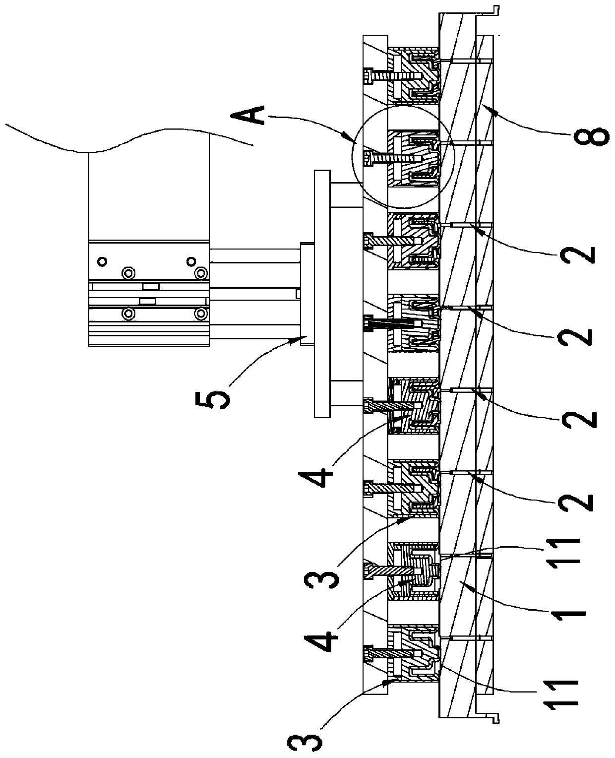
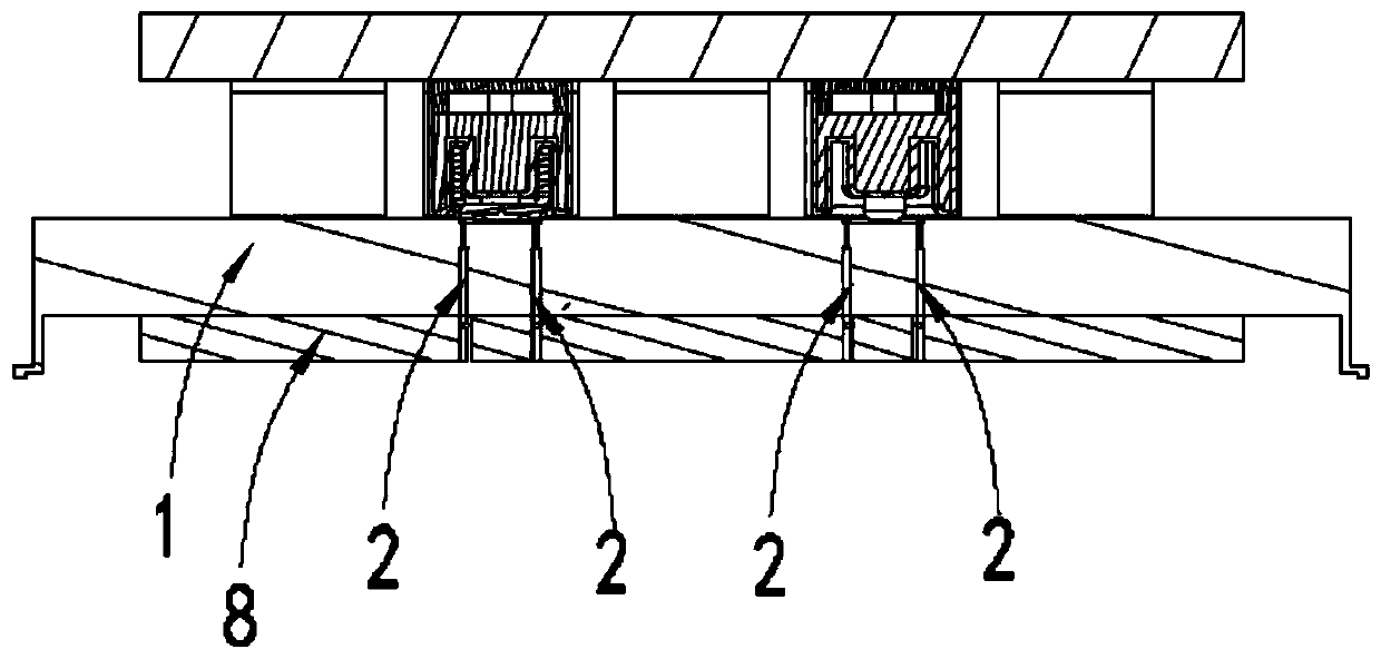
The invention discloses a dielectric barrier discharge plasma passivation device and a passivation method thereof, wherein the passivation device comprises an insulated support plate, a negative electrode, a barrier dielectric sleeve, a positive electrode and a moving device, at least one limiting groove is formed in the surface of the insulated support plate, the negative electrode is arranged onthe insulated support plate, is corresponding to the limiting groove in position and extends to a part above the bottom of the limiting groove, the barrier dielectric sleeve is located above the insulated support plate, the opening area at the lower end of the barrier dielectric sleeve can cover a notch of the limiting groove, the positive electrode is arranged in the barrier dielectric sleeve, and the moving device drives the barrier dielectric sleeve to move to a part right above the limiting groove and maintains a certain discharge air gap. In the solution, a workpiece can be used as the negative electrode, and is combined with the positive electrode that can be raised and lowered and the barrier dielectric sleeve, so that a plasma generated continuously between the metal workpiece andthe barrier dielectric sleeve under the constant pressure condition can directly clean the surface of the metal workpiece and forms a passivation layer on the surface of the workpiece by effectivelyusing the dielectric barrier discharge plasma priciple, which can greatly improves the corrosion resistance of the workpiece and prolong the service life of the workpiece.

Description

technical field [0001] The invention relates to the field of auto parts processing equipment, in particular to a dielectric barrier discharge plasma passivation device and a passivation method thereof. Background technique [0002] At present, for the finished coil casing (coil casing for automobile turbocharger, conductive metal material), it usually needs to be cleaned before packaging. [0003] One of the feasible cleaning processes includes the following process: ultrasonic cleaning-rinsing-industrial oven drying. [0004] Another feasible cleaning process includes the following processes: automatic spray cleaning - ultrasonic cleaning - spray rinsing - high pressure wind cutting water. [0005] Regardless of the process, the pollutants on the surface of the coil shell are often not completely removed, and the residual pollutants are likely to cause premature corrosion and rust of the product. [0006] With the development of other cleaning processes, such as plasma cl...

Claims


Application Information

Patent Timeline
Patent Type & Authority Applications(China)
IPC IPC(8): B08B7/00B08B13/00H05H1/24
CPCB08B7/00B08B13/00H05H1/2406Y02P70/50
Inventor 刘鑫培朱小刚刘慧敏
Owner SUZHOU CHUANGRUI MACHINERY & ELECTRICAL TECH
Learn More