
Liquid material evaporation numerical simulation method in spray drying tower and storage medium

A technology of spray drying tower and numerical simulation, which is applied in the field of numerical simulation method and storage medium of liquid material evaporation in spray drying tower, which can solve the problem of inability to obtain the temporal and spatial distribution of flow parameters, limit the improvement and design of spray drying equipment, and limit petroleum refining, etc. question

Pending Publication Date: 2020-05-08
CHINA PETROLEUM & CHEM CORP +1
View PDF0 Cites 2 Cited by
  • Summary
  • Abstract
  • Description
  • Claims
  • Application Information

AI Technical Summary

Problems solved by technology

The different parameters of the spray drying system, such as atomizing disc model and rotating speed, slurry flow rate, inlet air temperature, feed temperature, feed flow rate and hot air distributor, make the shape of the catalyst particles different, which in turn affects the activity and selectivity of the catalyst. , strength, resistance and heat transfer, etc., and the catalyst limits the refining of petroleum
[0005] Spray drying involves complex gas-liquid two-phase heat and mass transfer process. It is extremely difficult to measure directly in the drying tower, and it is impossible to directly manufacture a device for testing in large-scale industrial devices. Most of the models currently used are based on experience. Model or semi-empirical model, based on the experience of the designer and the small-scale scale-up of the experimental results of small devices, this method has limitations for mechanism analysis, cannot obtain the time-space distribution of flow parameters, and cannot fully describe the liquid material in the drying tower. The flow characteristics between the drying medium and the further improvement and design of the spray drying device are limited, which cannot meet the actual needs

Method used


Image

  • Liquid material evaporation numerical simulation method in spray drying tower and storage medium
  • Liquid material evaporation numerical simulation method in spray drying tower and storage medium
  • Liquid material evaporation numerical simulation method in spray drying tower and storage medium

Examples


Embodiment Construction

[0056] The specific implementation manners of the embodiments of the present invention will be described in detail below in conjunction with the accompanying drawings. It should be understood that the specific implementation manners described here are only used to illustrate and explain the embodiments of the present invention, and are not intended to limit the embodiments of the present invention.

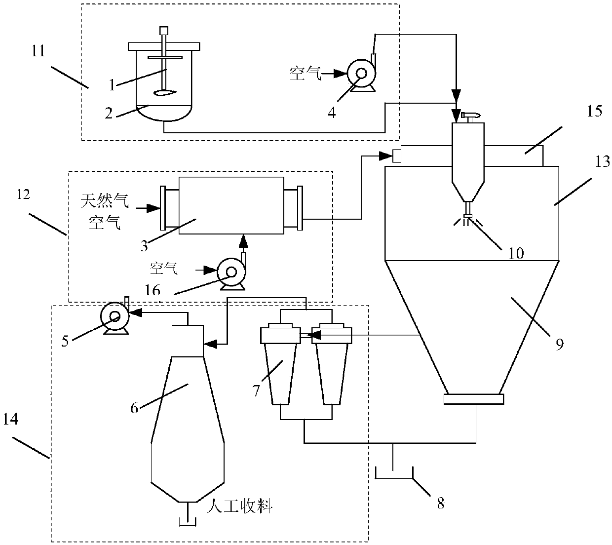
[0057] figure 1 It is a schematic diagram of the overall structure of the spray drying device provided by an embodiment of the present invention. The device includes: a feed liquid feeding device 11 for providing catalyst feed liquid. The feeding device includes: a stirring motor 1, a material storage tank 2 and a blower 4. The hot flue gas supply device 12 is used to provide hot flue gas. The gas supply device includes: the flue gas combustion chamber 3 and the blower 16; the spray drying tower 13 is used to receive the catalyst material provided by the feed liquid feeding device...


PUM


Abstract

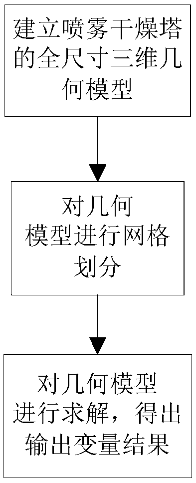
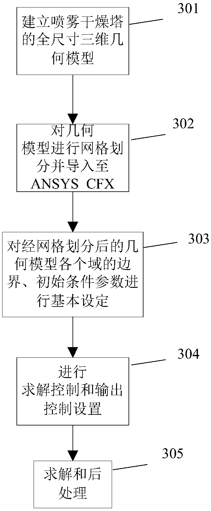
The embodiment of the invention provides a liquid material evaporation numerical simulation method in a spray drying tower and a storage medium, and belongs to the field of liquid material evaporation. Through the above technical scheme, the full-size three-dimensional geometric model of the spray drying tower is established according to the geometric parameters of the spray drying tower and meshgeneration is carried out; solving is carried out, an output variable result is obtained for analyzing the evaporation process of the liquid material; compared with the prior art that measurement cannot be directly carried out in a drying tower, a data result obtained by adopting experience of a designer and a method of carrying out small-scale trial amplification on an experimental result of a small device has deviation from an actual result, through establishing and solving a full-size three-dimensional geometric model of the spray drying tower, the obtained result is more precise.

Description

technical field [0001] The invention relates to the field of liquid material evaporation, in particular to a numerical simulation method and storage medium for liquid material evaporation in a spray drying tower. Background technique [0002] Spray drying system equipment is a new type of high-efficiency drying process equipment, which includes: [0003] It is used to dry solutions, emulsions, pastes and heat-sensitive materials. Generally, the water can evaporate within a few seconds to obtain powdery, granular hollow spheres or round granular products that meet production requirements. Spray drying technology has been widely used in the fields of food, chemical industry, medicine and environmental protection. With the development of modern technology, some technical industries related to the size of raw material particles, such as ceramics, chemical industry, additives and other industries, have strict requirements on the size of raw material particles , and further promo...

Claims


Application Information

Patent Timeline
Patent Type & Authority Applications(China)
IPC IPC(8): G06F30/20G06T17/00G06F17/11
CPCG06T17/00G06F17/11
Inventor 杜以村成伟陈世华孙裕苹
Owner CHINA PETROLEUM & CHEM CORP
Learn More