
Denitrification functional filler, and filler ball, filling method and applications thereof

A technology of functional fillers and filler balls, used in chemical instruments and methods, special compound water treatment, water/sludge/sewage treatment, etc., to achieve the effect of increasing biomass, low sludge production, and reducing production costs

Inactive Publication Date: 2020-05-12
清上(苏州)环境科技有限公司
View PDF13 Cites 9 Cited by
  • Summary
  • Abstract
  • Description
  • Claims
  • Application Information

AI Technical Summary

Problems solved by technology

[0040] CN 109607812 A "a compound denitrification agent" uses its own cultured microorganisms as the main body to add its suitable carbon source for denitrification, and at the same time uses physical methods to perform a small amount of adsorption denitrification, which belongs to the category of biological + physical denitrification , but if it needs to maintain long-term effective application, it still needs to continuously ensure the dosing of organic carbon sources

Method used


Image

  • Denitrification functional filler, and filler ball, filling method and applications thereof

Examples


Embodiment 1

[0071] Denitrification functional filler: 31.4 parts by weight of iron-carbon filler, 27.5 parts by weight of iron filings particles, 27.5 parts by weight of sulfur particles, and 7.8 parts by weight of biological activated carbon. Wherein the mass percent of each composition in the iron-carbon filler is iron: carbon: binding agent=88%: 8%: 4%, the iron-carbon filler is rugby ball shape, and its major axis radius is 8 ± 1cm, and minor axis radius is 3±0.5cm; the length and width of iron filings particles are 0.6cm, and the thickness is 0.06cm; the particle size of sulfur particles is about 0.2cm.

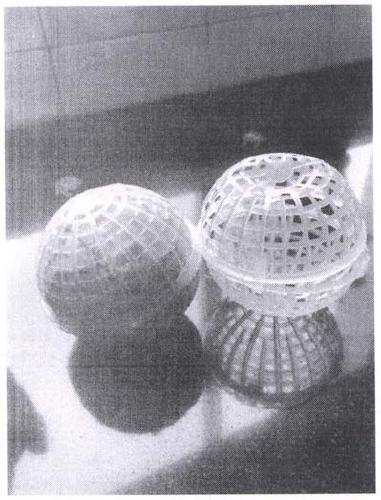
[0072] Filler balls: 3.9 parts by weight of anti-corrosion non-woven fabric, 2 parts by weight of filter balls.

[0073] The above-mentioned nitrogen-removing functional fillers are weighed, mixed completely, packed in anti-corrosion non-woven packing bags, and then packed into filter balls. After the packing balls are packaged, they need to be stored in a dry and low temperature p...

Embodiment 2

[0077] Denitrification functional filler: 31.4 parts by weight of iron-carbon filler, 27.5 parts by weight of iron filings particles, 27.5 parts by weight of sulfur particles, and 7.8 parts by weight of biological activated carbon. Wherein the mass percentage of each composition in the iron-carbon filler is iron: carbon: binding agent=88%: 8%: 4%, and the iron-carbon filler is rugby ball shape, and its major axis radius is 8 ± 1cm, and minor axis radius 3±0.5cm; the length and width of iron filings particles are 0.6cm, and the thickness is 0.06cm; the particle size of sulfur particles is about 0.2cm.

[0078] Filler balls: 3.9 parts by weight of anti-corrosion non-woven fabric, 2 parts by weight of filter balls.

[0079] The above-mentioned nitrogen-removing functional fillers are weighed, mixed completely, packed in anti-corrosion non-woven packing bags, and then packed into filter balls. After the packing balls are packaged, they need to be stored in a dry and low temperatu...


PUM

PropertyMeasurementUnit
Length and widthaaaaaaaaaa
Thicknessaaaaaaaaaa
Particle sizeaaaaaaaaaa

Abstract

The invention provides a denitrification functional filler, which comprises the following components in percentage by mass: 30-50% of an iron-carbon filler, 20-40% of scrap iron, 20-40% of sulfur and5-20% of biological active carbon. According to the invention, by using a novel autotrophic denitrification process of iron and sulfur, sludge production is low, the pH stability of a water body is maintained through a sulfur-iron coupling effect, and the problems of iron-based surface inert film generation and sulfur autotrophy alkalinity consumption in iron autotrophy are reduced; and the oxidation-reduction property of a biological active carbon functional group, and the conductivity, the high specific surface area and the biological activity of the main body are synchronously utilized, sothat the biomass in the system is improved, the denitrification efficiency of the system is improved, and finally the aims of reducing the operation cost and meeting the water quality requirement areachieved.

Description

technical field [0001] The invention belongs to the technical field of new water treatment materials, and in particular relates to a denitrification functional filler, a filler ball, a filling method and an application thereof. Background technique [0002] With the improvement of human living standards, the discharge of nitrogen-containing organic or inorganic compounds produced by human production and life increases, making NO in water bodies 3 - -N pollution is becoming more and more serious, resulting in the continuous deterioration of surface water quality, and the pollution problem is becoming more and more serious. Globally, surface water NO 3 - -N pollution is widely distributed and the degree of pollution is becoming more and more serious. NO 3 - -N pollution has become one of the most common pollution factors in global water bodies and is the most complex environmental problem in the world. NO in water 3 - -N mainly comes from urban domestic sewage, indust...

Claims


Application Information

Patent Timeline
IPC IPC(8): C02F3/28C02F101/16C02F101/38
CPCC02F3/2806C02F2101/16C02F2101/38C02F2305/06
Inventor 郭鹏王晶晶林重阳
Owner 清上(苏州)环境科技有限公司
Learn More