
Waste gas biological treatment device and control method thereof

A biological treatment and exhaust gas technology, applied in the direction of gas treatment, separation methods, chemical instruments and methods, etc., can solve problems such as unstable and reliable operation

Pending Publication Date: 2020-05-15
杭州楚环科技股份有限公司
View PDF3 Cites 0 Cited by
  • Summary
  • Abstract
  • Description
  • Claims
  • Application Information

AI Technical Summary

Problems solved by technology

[0005] Aiming at the technical problem that the biological treatment equipment in the prior art cannot operate stably and reliably when the pollutant load fluctuates continuously, the present invention proposes a waste gas biological treatment device and its control method

Method used


Image

  • Waste gas biological treatment device and control method thereof
  • Waste gas biological treatment device and control method thereof
  • Waste gas biological treatment device and control method thereof

Examples


Embodiment 1

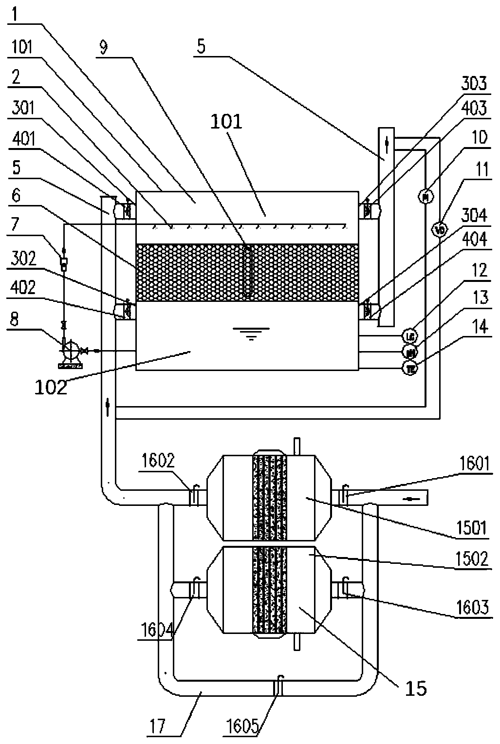
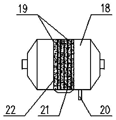
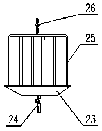
[0053] combine Figure 1-3 A waste gas biological treatment device proposed in this embodiment includes a biological filter tower 1 and a buffer unit. The biological filter tower 1 is provided with an air inlet and an air outlet, and the air outlet and the air inlet are connected to the first The two waste gas pipes are communicated, and the gas outlet is also communicated with the opening and the exhaust gas discharge port. The biological filter tower 1 is provided with a first chamber 101, a packed bed 6 and a second chamber 102, and the packed bed 6 is located in the first chamber. Between the chamber 101 and the second chamber 102, the first chamber 101 and the second chamber 102 are communicated through water pipes, and the buffer unit includes at least two buffer tanks 15 with adsorption and desorption functions, and for Across the bypass air pipe 17 of the buffer tank 15, one end of the two buffer tanks 15 is connected to the first exhaust gas pipe, and the other end of...

Embodiment 2

[0056] combine Figure 1-3, a kind of waste gas biological treatment device that present embodiment proposes, on the basis of embodiment 1, can make following improvement: described buffer tank 15 is provided with adsorbent bed 22, and described adsorbent bed 22 is provided with temperature control The device 20 and the heating device 21 are both connected to the controller. The heating device 21 is used to heat the adsorbent bed 22, which can be controlled by the controller to heat the adsorbent bed 22 according to the needs of the working conditions, thereby desorbing; the temperature control device 20 is used to detect the temperature of the adsorbent bed 22, which is controlled by the controller , so that the temperature of the adsorbent bed 22 is lower than 120° C., so as to realize the homogenization effect of the waste gas passing through the buffer tank 15 . The bypass air pipe 17 is provided with a ventilation valve 1605. When there are two buffer tanks 15, the first...

Embodiment 3

[0058] combine Figure 1-3 , a waste gas biological treatment device proposed in this embodiment, on the basis of Embodiment 1 or 2, the following improvements can be made: the packing bed 6 of the biological filter tower 1 is provided with a sight glass 9 . Observe the shape of the filler biofilm with the naked eye, and judge the quantity of the biofilm qualitatively.


PUM

PropertyMeasurementUnit
Diameteraaaaaaaaaa
Packing densityaaaaaaaaaa
Iodine valueaaaaaaaaaa

Abstract

The invention discloses a waste gas biological treatment device and a control method thereof, and belongs to the technical field of waste gas purification. The waste gas biological treatment device comprises a biological filter tower, and further comprises a buffer unit. The biological filter tower is provided with a gas inlet and a gas outlet, the gas outlet and the gas inlet are both communicated with a second waste gas pipe, and the gas outlet is also communicated with a pipeline for enabling an opening to be communicated with a waste gas exhaust port. A first chamber, a packed bed and a second chamber are arranged in the biological filter tower, and the packed bed is located between the first chamber and the second chamber. The buffer unit comprises at least two buffer tanks with adsorption and desorption functions and a bypass air pipe used for crossing the buffer tanks, one end of each of the two buffer tanks is communicated with a first waste gas pipe, and the other end of eachof the two buffer tanks is communicated with the second waste gas pipe. Aiming at the technical problem that biological treatment equipment in the prior art cannot stably and reliably operate when thepollutant load continuously fluctuates greatly, the function of resisting the pollutant impact load can be realized.

Description

technical field [0001] The invention relates to the technical field of exhaust gas purification, in particular to an exhaust gas biological treatment device and a control method thereof. Background technique [0002] Waste gas biological purification technology uses the metabolism of microorganisms attached to the filler to convert harmful substances in the waste gas into cell components and small molecular substances such as water and carbon dioxide. It has the advantages of high efficiency, low consumption, mild reaction conditions, and no secondary pollution. It is especially suitable for treating low-to-medium concentration, high-volume organic and odorous waste gas with no recovery value. [0003] It is a difficult problem to maintain the efficient and stable operation of the biological treatment device under the impact load of pollutants. At this stage, waste gas biological purification technology has been widely used in areas with relatively stable pollutant loads, s...

Claims


Application Information

Patent Timeline
IPC IPC(8): B01D53/85B01D53/44B01D53/04
CPCB01D53/85B01D53/44B01D53/04B01D2257/708B01D2251/95Y02A50/20
Inventor 陈步东金顺利曹飞飞
Owner 杭州楚环科技股份有限公司
Learn More