Method and implementation device for bipolar electrolytic electrolytic machining of workpieces

A technology for electrolytic discharge and workpiece machining, applied in the method and implementation device, in the field of bipolar electrolytic discharge machining workpiece, can solve the problems of low machining efficiency, low machining energy, low electrolytic machining efficiency and the like

Active Publication Date: 2020-11-03
SOUTH UNIVERSITY OF SCIENCE AND TECHNOLOGY OF CHINA
View PDF5 Cites 0 Cited by
  • Summary
  • Abstract
  • Description
  • Claims
  • Application Information

AI Technical Summary

Problems solved by technology

In the method of electrolytic machining of microelectrodes, there is a certain gap between the tool electrode and the workpiece. The smaller the machining gap, the higher the machining accuracy. Generally, the machining gap is at the micron level, but the smaller the electrolytic machining gap, the lower the processing energy, which will lead to machining efficiency. Low, that is, it shows the result of low ECM efficiency

Method used


Image

  • Method and implementation device for bipolar electrolytic electrolytic machining of workpieces
  • Method and implementation device for bipolar electrolytic electrolytic machining of workpieces
  • Method and implementation device for bipolar electrolytic electrolytic machining of workpieces

Examples


Embodiment 1

[0030] An embodiment of the present invention provides a method for bipolar electrolytic electrolytic machining of workpieces, comprising the following steps:

[0031] (1) Provide power supply, the positive pole of the power supply is connected to the conductive workpiece, and the negative pole of the power supply is connected to the conductive electrode;

[0032] (2) soak the conductive workpiece and the conductive electrode in the electrolyte;

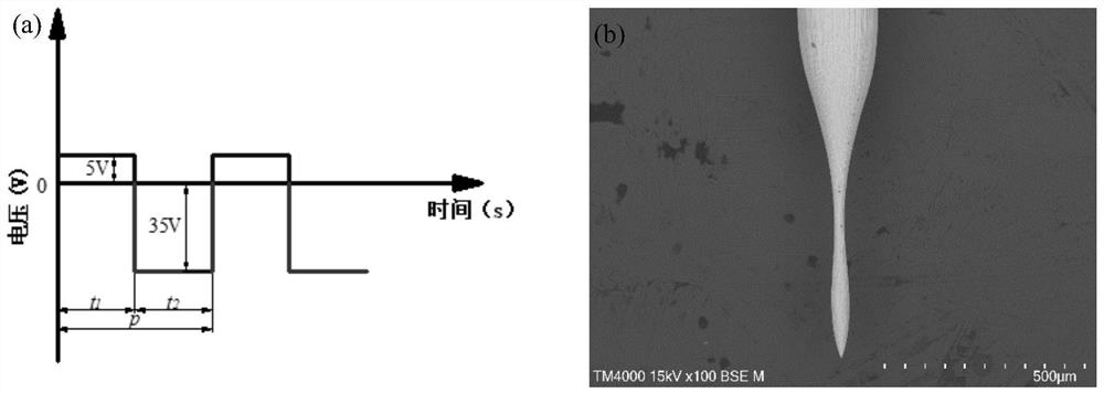
[0033] (3) Turn on the power supply to process the conductive workpiece, the power supply outputs bipolar pulse voltage, and the voltage value of the negative polarity voltage is greater than 25V.

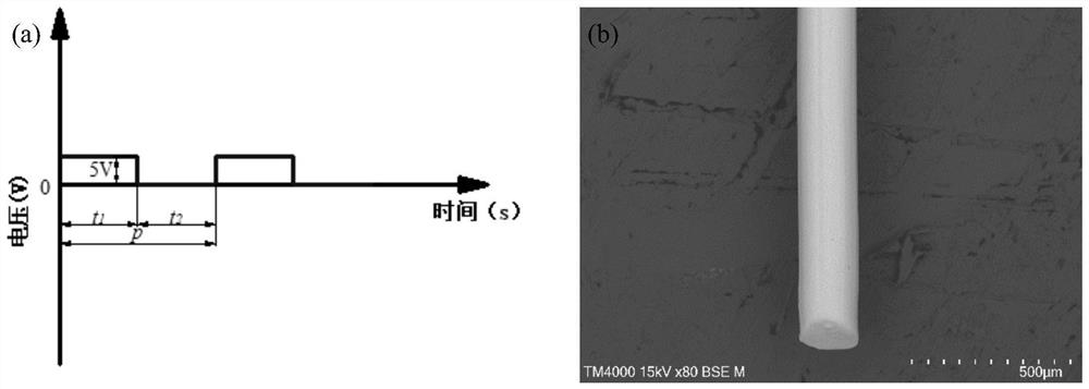
[0034] In this embodiment, the conductive workpiece is a tungsten rod with a diameter of 200 μm, the conductive electrode is a graphite plate of 50 mm*30 mm*5 mm, and the electrolyte is 20% NaOH solution.

[0035] In order to compare the effect of the method for conventional electrolytic machining of workpieces and the method of bipolar ...

Embodiment 2

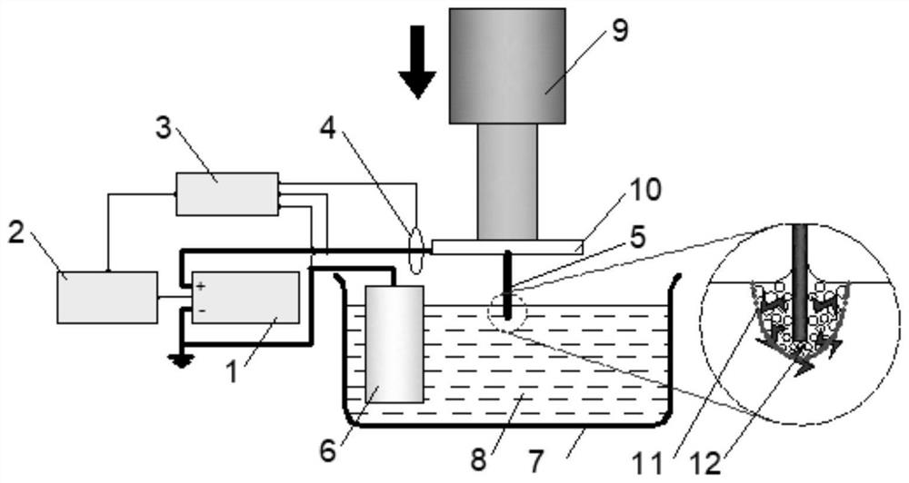
[0040] This embodiment provides an implementation device for implementing the method for bipolar EDM workpieces, see image 3 , the implementation device includes a power supply system, the power supply system includes an electrically connected bipolar pulse power supply 1, a pulse generator 2, an oscilloscope 3 and a current probe 4 for monitoring, and the power supply system is adjusted to output bipolar Pulse voltage, bipolar pulse voltage includes positive polarity voltage and negative polarity voltage, the voltage value of the negative polarity voltage is greater than 25V, the positive pole of the power supply system is connected to the conductive workpiece 5, and the negative pole of the power supply system is connected to the conductive electrode 6; the implementation device also includes Working fluid system. The working fluid system includes a processing tank 7, which is used to contain an electrolyte 8. In the working state, the conductive workpiece 5 and the conducti...


PUM


Abstract

The invention discloses a method for bipolar electrolysis discharging machining of parts and an implementing device. The method for bipolar electrolysis discharging machining of parts comprises the following steps that a power source is supplied, wherein a positive electrode of the power source is connected with a conductive workpiece, and a negative electrode of the power source is connected witha conductive electrode; the conductive workpiece and the conductive electrode are soaked with an electrolyte; the power source is turned on to machine the conductive workpiece, the power source outputs bipolar pulse voltage, the bipolar pulse voltage includes positive polarity voltage and negative polarity voltage, and the voltage value of the negative polarity voltage is larger than 25 V. The positive polarity voltage is used for oxidizing and corroding the conductive workpiece, the negative polarity voltage is used for generating spark, the electrolysis discharging efficiency of an electrode in the positive polarity voltage pulse period is improved, and the high machining efficiency can still be achieved under the centimeter-scale machining interval.

Description

technical field [0001] The invention relates to the technical field of electrode processing, in particular to a method and an implementation device for bipolar electrolytic electrolytic machining of workpieces. Background technique [0002] At present, a large number of micropore and microgroove structures are used in microelectromechanical systems, biomedicine, precision molds, and high-end watch dials, where the pore diameter or groove width is generally between 10 and 100 μm. This type of surface microstructure has the characteristics of small structure size, large number of arrays, high processing precision requirements, and high surface quality requirements, making its processing problems a key factor restricting product performance and large-scale applications. In the surface microstructure processing method, the traditional drilling and milling processing size is generally above 100 μm. When facing smaller size processing, due to the difficulty in manufacturing the to...

Claims


Application Information

Patent Timeline
Patent Type & Authority Patents(China)
IPC IPC(8): B23H5/02
CPCB23H5/02
Inventor 赵永华詹顺达关均铭
Owner SOUTH UNIVERSITY OF SCIENCE AND TECHNOLOGY OF CHINA
Why Eureka
Try Eureka