
An improved method for the preparation of ion beam sputtering coating plugging sensor

An ion beam sputtering and sensor technology, which is applied in sputtering coating, ion implantation coating, welding equipment, etc., can solve the problems of random sensor breaking position, lower production efficiency and product quality, and lower product reliability. Achieve the effects of resistance consistency and controllability of breaking position, production efficiency and product quality, performance and reliability

Active Publication Date: 2021-09-24
SHAANXI ELECTRICAL APPLIANCE RES INST
View PDF12 Cites 0 Cited by
  • Summary
  • Abstract
  • Description
  • Claims
  • Application Information

AI Technical Summary

Problems solved by technology

[0004] (1) There is no lead wire welding positioning structure design in the structural design of the sensor, which will lead to inconvenient welding operation and poor consistency of resistance value caused by welding deviation;
[0005] (2) There is no pull-off position positioning structure design in the structural design of the sensor. When the engine is ignited and the sensor is pulled off, the pull-off position of each sensor will be random, making it uncontrollable;
However, since the thickness of the conductive film is relatively thin, and the surface of the Cu film is prone to oxidation, creases are easily generated in the free bending state, which reduces the reliability of the product;
[0007] (4) The process of depositing the same metal film at the same time as the conductive pattern film layer and the edge frame metal film, because the conductive pattern film layer is thicker, it takes a long time to clean the excess film between the edge frame metal film and the conductive pattern film, and the cleaning is not clean The edge sawtooth caused by secondary manual processing is required, which reduces production efficiency and product quality;
[0008] (5) The conductive pattern film layer (Cu) adopts silicon nitride Si 3 N 4 The protective film is used for protection. Due to the poor ductility of the silicon nitride dielectric film, cracks will appear in the dielectric film during the tensile test, resulting in reduced protection and affecting product quality.

Method used


Image

  • An improved method for the preparation of ion beam sputtering coating plugging sensor
  • An improved method for the preparation of ion beam sputtering coating plugging sensor
  • An improved method for the preparation of ion beam sputtering coating plugging sensor

Examples


Embodiment Construction

[0035] The present invention will be described in detail below with reference to the accompanying drawings and two embodiments.

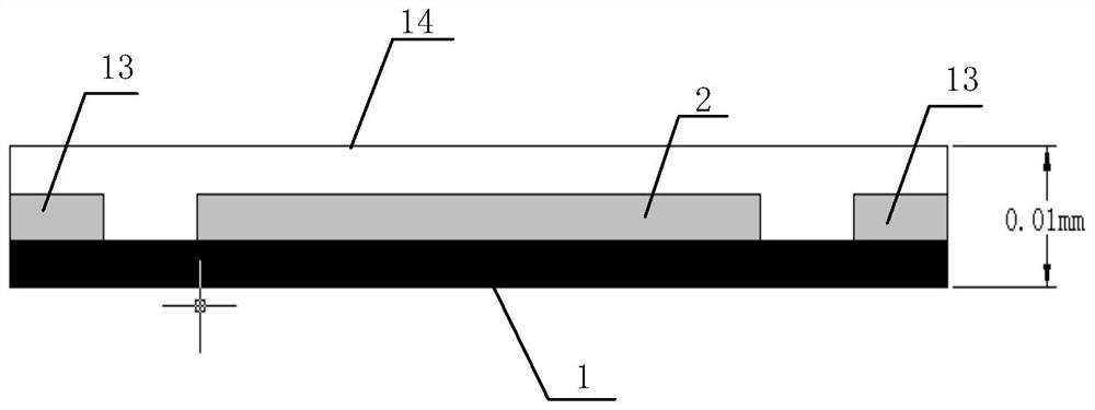
[0036] Such as figure 1 As shown, the present invention provides an improved method for preparing an ion beam sputtered film-coated blocking sensor, and the present invention further designs a positioning hole for a welding lead wire and a positioning hole for a breaking position. And in the film deposition process design of the conductive pattern, a new film structure design of a layer of copper and constantan is deposited. Its specific implementation is as figure 1 Shown:

[0037] Step 1, polyimide is used as a substrate, and the thickness of the substrate is 50 μm. Ultrasonic cleaning with cleaning agent, then rinse with water and dry;

[0038] Step two, such as Figures 2 to 4 As shown, design a paddle-like structure 2 with left and right sides wide and narrow in the middle, and a first pull-off position positioning hole 3 and a second pull...


PUM

PropertyMeasurementUnit
thicknessaaaaaaaaaa
thicknessaaaaaaaaaa
thicknessaaaaaaaaaa

Abstract

The invention discloses an improved preparation method of an ion beam sputtering coating blocking sheet sensor. In the structural design of the sensor designed in the present invention, the design of the lead wire welding positioning structure and the breaking position mechanism are added, which not only improves the operability of welding, but also significantly improves the consistency of the resistance value and the controllability of the breaking position .

Description

technical field [0001] The invention relates to an improved preparation method of an ion beam sputtering film-coated blocking sensor, which belongs to the field of sensor measuring devices. Background technique [0002] In recent years, with the development of aerospace vehicle technology, in order to realize the detection of the opening signal of the engine block, it is necessary to provide a sensor based on a flexible substrate. The two ends of the sensor are respectively connected to the nozzle of the engine for the control system to perform Blocking plate opening signal detection, when the engine is ignited, the pressure in the combustion chamber increases rapidly to a certain value, the sensor’s blocking plate is opened, and the sensor is pulled off, thereby providing an opening signal to the control system. [0003] At present, the plugging sensor commonly used in this field is a structure in which the strain gauge sensitive layer is directly pasted on the substrate wi...

Claims


Application Information

Patent Timeline
Patent Type & Authority Patents(China)
IPC IPC(8): G01B7/16C23C14/46B23K37/04B05C3/18
CPCB05C3/18B23K37/0435C23C14/46G01B7/16
Inventor 戚云娟李大全毛昭勇潘婷郭姗姗张苗
Owner SHAANXI ELECTRICAL APPLIANCE RES INST
Learn More