
Fluorescence lifetime measurement mode based on successive comparison method

A technology of fluorescence lifetime and measurement method, applied to the field of CMOS imaging, can solve problems such as limiting the imaging frame rate of image sensors, and achieve the effect of reducing the amount of effective data, saving output bandwidth, and reducing bandwidth pressure

Inactive Publication Date: 2020-05-19
TIANJIN UNIV MARINE TECH RES INST
View PDF4 Cites 0 Cited by
  • Summary
  • Abstract
  • Description
  • Claims
  • Application Information

AI Technical Summary

Problems solved by technology

However, in these three methods, after the high-frequency pulsed laser excites the fluorophore, the photodetection unit will generate a large amount of data, which needs to be processed immediately.
This puts a lot of pressure on the output bandwidth of the sensor and severely limits the imaging frame rate of the image sensor

Method used


Image

  • Fluorescence lifetime measurement mode based on successive comparison method
  • Fluorescence lifetime measurement mode based on successive comparison method
  • Fluorescence lifetime measurement mode based on successive comparison method

Examples


Embodiment Construction

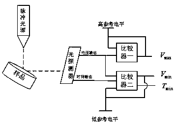
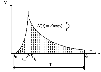
[0018] The pulse light source described in the present invention can use the near-infrared light source of wavelength at 700nm-900nm, and photodetector can adopt The single-electron avalanche diode array, the analog domain comparator can be composed of a five-tube comparator and a CD4051 multi-channel selector, and the whole circuit can be based on -Manufactured by CMOS process, all measurement time T is set to 5ns, each exposure time Set to 50ps. The pulsed laser irradiating the sample starts at the same time as the system exposure, and the pulsed laser irradiating the sample is not longer than 50 ps. After the entire measurement period is over, a more accurate fluorescence lifetime measurement result can be obtained.

[0019] For example, we use a light source with a wavelength of 900nm to excite the sample, and the sample is labeled with 4',6-diamidino-2-phenylindole. The irradiation time of the excitation light source to the sample is 50 ps, ​​and each exposure cycle...


PUM

PropertyMeasurementUnit
wavelengthaaaaaaaaaa

Abstract

According to a fluorescence lifetime measurement mode based on a successive comparison method, voltage signals output by an optical detection unit are compared in real time and accepted or rejected mainly through an analog domain comparator so that the final output signals only comprise the highest voltage signal, the lowest voltage signal and a time signal, an effective data volume output by thesensor is greatly reduced, and bandwidth pressure is reduced.

Description

technical field [0001] The invention relates to the field of CMOS imaging, in particular to a fluorescence lifetime measurement method based on a successive comparison method. Background technique [0002] Fluorescence lifetime imaging is a method of microscopic imaging using the decay curve of a fluorophore after it is excited. This fluorescence imaging method will not be affected by factors such as too short Stokes distance, environmental autofluorescence, uneven concentration of fluorophores, and different optical pathways, but only depends on the physical and chemical environment of the fluorophore, so it is used It is widely used in modern medicine and life science research, such as detecting the delivery and absorption of drugs in the blood, detecting the spread of cancer cells, etc. [0003] The current fluorescence lifetime imaging methods mainly include time-correlated single-photon counting method, gated image enhancement and phasor method in frequency domain. Ho...

Claims


Application Information

Patent Timeline
Patent Type & Authority Applications(China)
IPC IPC(8): G01N21/64
CPCG01N21/6489
Inventor 徐江涛查万斌聂凯明林鹏顾天宇
Owner TIANJIN UNIV MARINE TECH RES INST
Learn More