Preparation method of selective emitter battery

An emitter and selective technology, applied in photovoltaic power generation, circuits, electrical components, etc., can solve the problems of large damage area of ​​cells and insufficient uniformity of laser spot, etc., achieve low equipment cost, improve cell conversion efficiency, reduce The effect of damage area

Pending Publication Date: 2020-05-19
TIANJIN AIKO SOLAR ENERGY TECH CO LTD
View PDF11 Cites 6 Cited by
  • Summary
  • Abstract
  • Description
  • Claims
  • Application Information

AI Technical Summary

Problems solved by technology

However, when the existing selective emitter cells are doped with lasers, there is insufficient uniformity of the laser spot and a large damage area to the cells, so that there is still room for further improvement in the conversion efficiency of the cells.

Method used

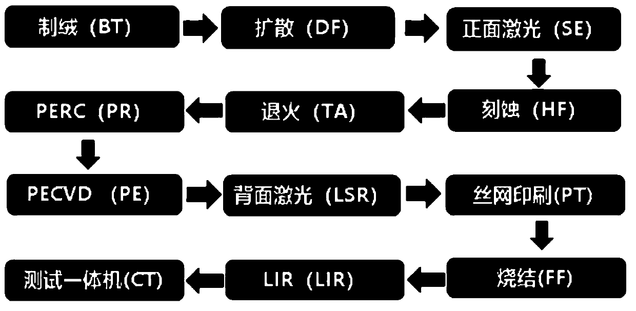
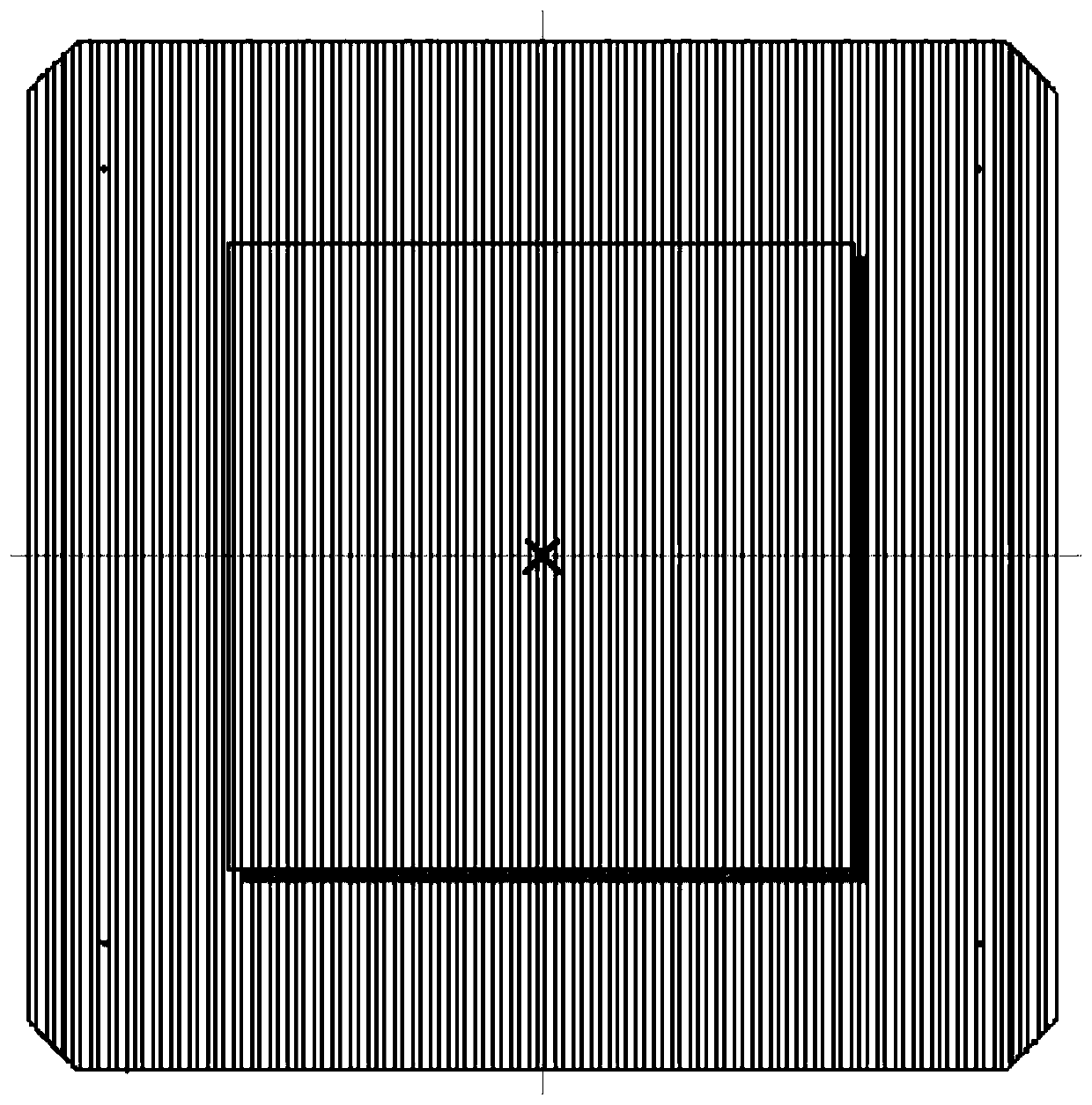
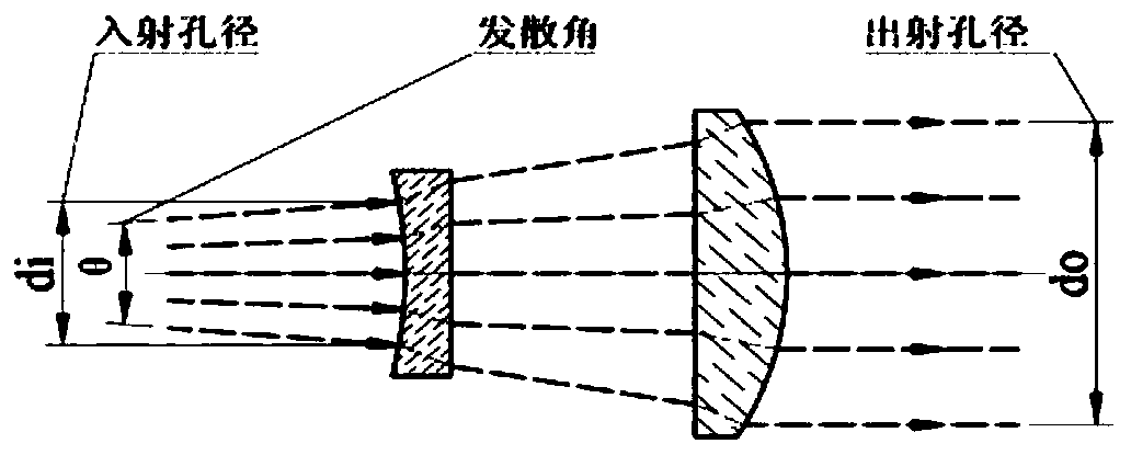

Image

  • Preparation method of selective emitter battery
  • Preparation method of selective emitter battery
  • Preparation method of selective emitter battery

Examples


Embodiment Construction

[0027] The present invention will be further described below in conjunction with specific examples, so that those skilled in the art can better understand and implement the technical solutions of the present invention.

[0028] The mechanism of the embodiment of the present invention to improve the battery conversion effect is as follows:

[0029] The particles are in the ground state at room temperature, and energy needs to be injected by the pump source to pump a large amount of particles to the excited state, and the inversion of the number of particles in the upper and lower energy levels creates the necessary conditions for the generation of laser light. The population inversion is only a necessary condition for generating stimulated radiation, and it cannot generate laser light. Only by placing the active material in the optical resonant cavity and selecting the frequency and direction of light can continuous light amplification and laser oscillation output be obtained. ...


PUM

PropertyMeasurementUnit
wavelengthaaaaaaaaaa
thicknessaaaaaaaaaa

Abstract

The invention provides a preparation method of a selective emitter battery. The method comprises the steps of forming a PN junction through diffusion of a doping source and manufacturing a selective emitter through laser doping, and is characterized in that in the step of manufacturing the selective emitter through laser doping, enriching elements doped in a region by changing the energy and the light spot size of laser irradiating the region to be metalized on a silicon wafer, and forming the selective emitter. According to the preparation method of the selective emitter battery, the damage area of the laser to the battery piece is reduced by adjusting the energy of the laser and the size of a light spot, different doped regions of the SE in a grid line contact region and a non-contact region are realized, and meanwhile, the battery efficiency is improved.

Description

technical field [0001] The invention belongs to the technical field of solar cell preparation, and in particular relates to a method for preparing a selective emitter cell. Background technique [0002] When non-renewable energy sources such as electricity, coal, and petroleum are frequently running out, and energy issues have increasingly become a bottleneck restricting the development of the international society and economy, more and more countries have begun to implement the "Sunshine Plan" to develop solar energy resources and seek new impetus for economic development. Some high-level nuclear research institutions in Europe have also begun to turn to renewable energy. Driven by the huge potential of the international photovoltaic market, the solar cell manufacturing industries of various countries are scrambling to invest huge sums of money and expand production in order to compete for a place. [0003] With the continuous development of the photovoltaic industry, the ...

Claims


Application Information

Patent Timeline
Patent Type & Authority Applications(China)
IPC IPC(8): H01L31/0224H01L31/042
CPCH01L31/022425H01L31/042Y02E10/50
Inventor 赵小平杨二存夏利鹏李吉刘海泉高丽丽郭星妙
Owner TIANJIN AIKO SOLAR ENERGY TECH CO LTD
Why Eureka
Try Eureka