Jet-type thermal degreasing flux pre-coating continuous production line

A thermal degreasing and jet-type technology, applied in the direction of coating, spraying device, pretreatment surface, etc., can solve the problems of great environmental hazards, discharge of undesirable substances, and large equipment loss, etc., to eliminate potential safety hazards, reduce heat consumption, reduce The effect of energy consumption

Active Publication Date: 2021-09-28
盐城市苏文机械有限公司
View PDF0 Cites 0 Cited by
  • Summary
  • Abstract
  • Description
  • Claims
  • Application Information

AI Technical Summary

Problems solved by technology

[0002] At present, the oily exhaust gas produced by the commonly used metal surface thermal degreasing equipment is directly discharged, which directly pollutes the environment and wastes a lot of energy due to the high temperature of the exhaust gas
There is also a way to incinerate oily waste gas to solve the problem of soot pollution. Since volatile oil is flammable and explosive, the oil content in the waste gas is relatively low. It is necessary to heat a large amount of oily air to above 800°C for incineration, which consumes a lot of energy and equipment loss. Due to the large temperature stability and insufficient time effect, the exhaust gas is easily decomposed to produce undesirable substances (such as dioxins) and secondary pollution occurs; currently, the flux coating produces a large amount of flux-containing exhaust gas, which is harmful to the environment. It is more harmful, and it is generally discharged by direct filtration.
We know that the brazing flux contains 70-80% of water and some adhesives. It is a wet mixture containing high-viscosity particles. It will gradually block the filter device during work, making it impossible to discharge exhaust gas smoothly and cause internal overflow pollution.
Only frequent cleaning of the filter device will produce a large amount of sewage and dirt from cleaning

Method used


Image

  • Jet-type thermal degreasing flux pre-coating continuous production line
  • Jet-type thermal degreasing flux pre-coating continuous production line

Examples


Embodiment Construction

[0017] The following will clearly and completely describe the technical solutions in the embodiments of the present invention with reference to the accompanying drawings in the embodiments of the present invention. Obviously, the described embodiments are only some, not all, embodiments of the present invention.

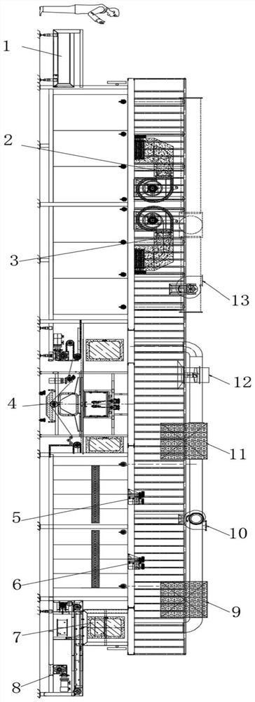
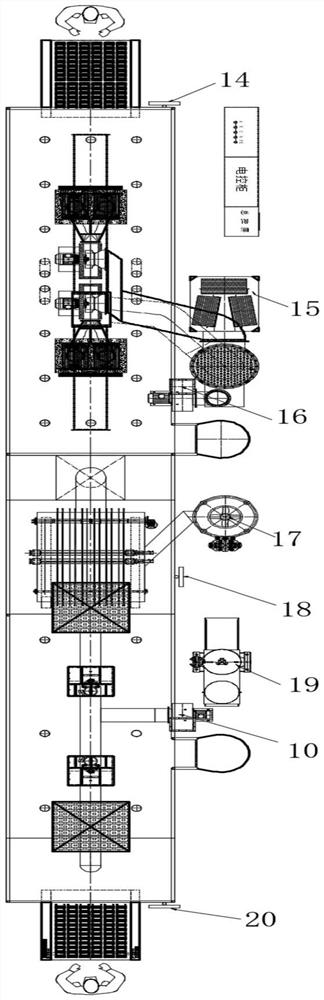
[0018] refer to Figure 1-2 , Jet-type heat degreasing flux pre-coating continuous production line, including the upper part system 1, the first air knife degreasing device 2, and the second air knife degreasing device 3, which are arranged on the workbench in sequence. For small aluminum plates, fresh hot air is used The spraying method maximizes the removal of volatile oil contained in the surface of the workpiece. The entrance of the degreasing equipment is equipped with an upper section station, and the middle section of the furnace body is equipped with a maintenance inspection door. The movable insulation cover and the waste gas discharge ports are set in each ...


PUM


Abstract

The invention discloses a jet-type thermal degreasing flux pre-coating continuous production line, which includes an upper part system, a first air knife degreasing device, a second air knife degreasing device, an automatic flux coating system, and a second air knife degreasing device arranged on the worktable in sequence. The first drying circulation fan, the second drying circulation fan, air cooling system, output system, drying cooling exhaust filter, drying cooling exhaust fan, degreasing cooling exhaust filter, spraying purification exhaust fan, heat exchange exhaust fan, upper parts Control panel, air inlet filter, exhaust fan, coating purification exhaust fan, coating control panel, flux system, and output control panel. For small-sized aluminum plates, the present invention adopts the fresh hot air spraying method to remove the volatile oil contained in the surface of the workpiece to the greatest extent; the surface of the hot workpiece after degreasing is sprayed with flux, and the heat carried by the workpiece can be calculated according to the constant pre-spray flux. The brazing flux concentrates quickly and stably, without flowing and lace phenomenon. It also provides conditions for the drying furnace to reduce energy consumption.

Description

technical field [0001] The invention relates to the field of mechanical technology, in particular to a continuous production line for pre-coating jet-type thermal degreasing flux. Background technique [0002] At present, the oily waste gas produced by the commonly used metal surface thermal degreasing equipment is directly discharged, which directly pollutes the environment and wastes a lot of energy due to the high temperature of the waste gas. There is also a way to incinerate oily waste gas to solve the problem of soot pollution. Since volatile oil is flammable and explosive, the oil content in the waste gas is relatively low. It is necessary to heat a large amount of oily air to above 800°C for incineration, which consumes a lot of energy and equipment loss. Due to the large temperature stability and insufficient time effect, the exhaust gas is easily decomposed to produce undesirable substances (such as dioxins) and secondary pollution occurs; currently, the flux coati...

Claims


Application Information

Patent Timeline
Patent Type & Authority Patents(China)
IPC IPC(8): B05B16/20B05D3/00B08B5/02B08B13/00
CPCB05D3/002B08B5/02B08B13/00B05B16/20Y02P70/10
Inventor 林梓生
Owner 盐城市苏文机械有限公司
Why Eureka
Try Eureka