Sintering flue gas desulfurization and denitrification process

A technology for sintering flue gas, desulfurization and denitrification, applied in the field of metallurgical industry, can solve the problems of high denitration cost, high operation cost, secondary pollution, etc., and achieve the effect of ensuring denitration effect, realizing rational utilization, and saving energy consumption.

Active Publication Date: 2020-05-29
CENT IRON & STEEL RES INST +1
View PDF11 Cites 4 Cited by
  • Summary
  • Abstract
  • Description
  • Claims
  • Application Information

AI Technical Summary

Problems solved by technology

Among them, the activated coke desulfurization and denitrification process can meet the ultra-low emission requirements, but its investment is high and the operating cost is high; the "dry (semi-dry) desulfurization + flue gas heating + denitrification" process has a smaller investment than the active coke desulfurization and denitrification process , but the flue gas needs to be heated by supplementary combustion, which consumes a large amount of gas, so the denitrification cost is also high; the implementation method of the flue gas oxidative desulfurization and denitrification process is simple, but it uses ozone as an oxidant to oxidize NO, which is easy to cause ozone emissions , causing secondary pollution

Method used


Image

  • Sintering flue gas desulfurization and denitrification process
  • Sintering flue gas desulfurization and denitrification process
  • Sintering flue gas desulfurization and denitrification process

Examples


Embodiment 1

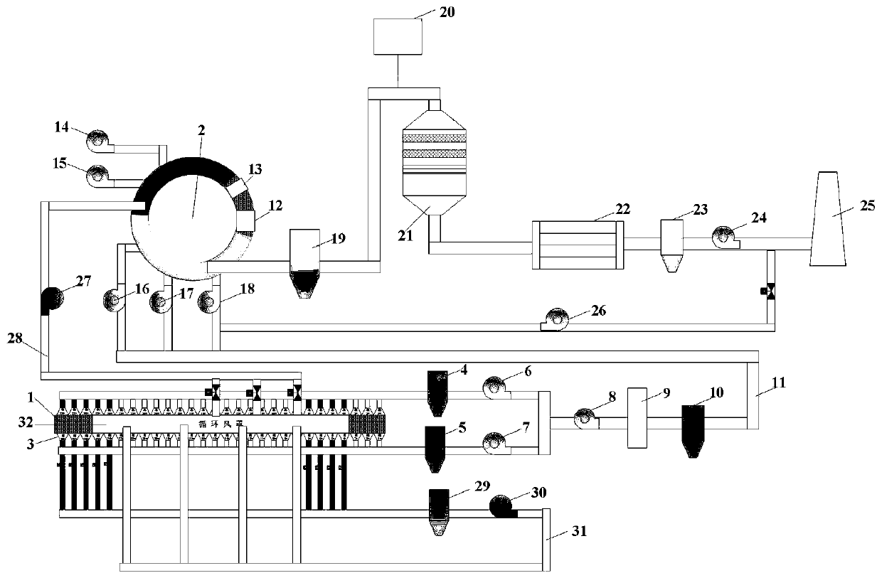
[0084] Such as figure 1 As shown, the sintering flue gas desulfurization and denitrification device used in the sintering flue gas desulfurization and denitration process provided in this embodiment includes a 400m 2 Sintering machine 1, 28 bellows 3 on each side of the upper and lower sides of sintering machine 1, of which the upper bellows are compiled from right to left as A1-A28, and the lower bellows are compiled from right to left as B1-B28, and A4- The A7, B4-B7, A24-A28, B24-B28 wind boxes are directly connected to the circulating flue 31. This configuration can achieve a flue gas circulation volume of 31%, and the oxygen content in the circulating flue gas> 18%, temperature> 180℃, so by using this part of the flue gas sensible heat can reduce the energy consumption of the sintering machine, saving energy> 1%, the quality of sintered ore can be ensured by controlling the proper oxygen concentration of the circulating flue gas as the gas source. This arrangement enables pa...

Embodiment 2

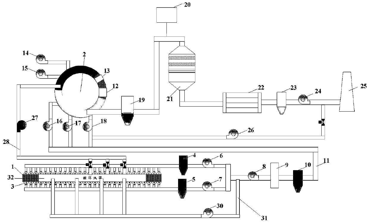
[0091] Such as figure 2 As shown, the sintering flue gas desulfurization and denitration device used in the sintering flue gas desulfurization and denitration process provided in this embodiment includes a 360m 2 Sintering machine 1, 28 wind boxes 3 on each side of the upper and lower sides of the sintering machine 1. The upper wind boxes are connected to flue A. The first dust collector 4 and the first main exhaust fan 6 are arranged in the flue A. The lower wind boxes are all Connected to flue B, flue B is provided with a second dust collector 5 and a second main exhaust fan 7 in sequence, flue A and flue B are combined and connected to circulating flue 31 and main flue gas pipe 11 through a three-way unit ; The arrangement on the main flue gas pipe 11 is the same as that of the first embodiment, and will not be repeated here.

[0092] Specifically, a circulating fan 30 is provided on the circulating flue 31, and the flue gas passes through the circulating fan 30 and reaches th...

Embodiment 3

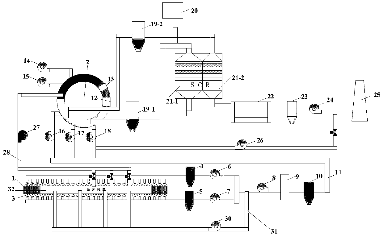
[0097] Such as image 3 As shown, the difference between the sintering flue gas desulfurization and denitrification device provided in this embodiment and the second embodiment is that the boiler in the waste heat recovery unit 22 is a dual-pressure boiler, so there are two flue gases with different temperatures when entering the waste heat recovery unit 22 The high-temperature section of the annular cooler has two flue gas outlets; the flue gas leads out two flue gases from the hood of the high-temperature section of the annular cooler 2. The flue gas temperature of one way is higher, and the flue gas temperature is 400℃. The gas passes through the first high-temperature dust collector 19-1 for coarse dust removal, and then enters the first denitration reactor 21-1 for denitration, and then enters the first heat exchange tube in the boiler in the waste heat recovery unit 22 after denitration; The flue gas temperature is 270°C. The flue gas firstly passes through the second high...


PUM


Abstract

The invention discloses a sintering flue gas desulfurization and denitrification process, belongs to the field of metallurgical industry, and solves the problems of large investment and high operationcost of the sintering flue gas desulfurization and denitrification process in the prior art. The method comprises the following steps that sintering flue gas of a sintering machine is divided into flue gas needing desulfurization and denitrification and circulating flue gas through a flue gas circulation process; flue gas to be desulfurized and denitrified is desulfurized after being desulfurizedand pressurized, and the desulfurized flue gas is subjected to dust removal; the dedusted flue gas is blown into the high-temperature section material layer of the circular cooler from an air blowerat the high-temperature section of the circular cooler to exchange heat with hot sinter for heating; the flue gas subjected to heat exchange and temperature rise is subjected to coarse dust removal and then enters a denitration reactor for denitration; the denitrated flue gas enters a waste heat recovery unit to be cooled, and the cooled flue gas is subjected to dust removal firstly and then is led out by an induced draft fan; and the led-out flue gas is directly discharged from a chimney. The process is low in cost, energy-saving and suitable for desulfurization and denitrification treatmentof sintering flue gas.

Description

Technical field [0001] The invention relates to the field of metallurgical industry, in particular to a sintering flue gas desulfurization and denitration process. Background technique [0002] Sintering flue gas is a pollutant-containing waste gas produced in the production process of sintering machines. At present, iron and steel enterprises are undergoing ultra-low emission desulfurization, denitrification and dust removal transformations. The SO 2 Concentration at 35mg / Nm 3 Within, NO x Concentration at 50mg / Nm 3 Within, the concentration of fine particles is 10mg / Nm 3 Within. [0003] The existing desulfurization and denitrification processes mainly include activated coke desulfurization and denitrification processes, "dry (semi-dry) desulfurization + flue gas supplementary heating + denitrification" processes, and flue gas oxidative desulfurization and denitration processes. Among them, the activated coke desulfurization and denitration process can meet the ultra-low emission...

Claims


Application Information

Patent Timeline
Patent Type & Authority Applications(China)
IPC IPC(8): B01D53/75B01D53/80B01D53/50B01D53/86B01D53/56B01D50/00F27D17/00
CPCB01D50/00B01D53/50B01D53/75B01D53/80B01D53/8631B01D2251/2062B01D2258/0283F27D17/001F27D17/004F27D17/008F27M2003/04Y02P10/25
Inventor 王锋齐渊洪王海风周和敏严定鎏林万舟
Owner CENT IRON & STEEL RES INST
Why Eureka
Try Eureka