
Gate voltage control

A gate, working voltage technology, used in circuits, electrical components, electronic switches, etc.

Pending Publication Date: 2020-05-29
NXP BV
View PDF10 Cites 0 Cited by
  • Summary
  • Abstract
  • Description
  • Claims
  • Application Information

AI Technical Summary

Problems solved by technology

[0003] These and other issues have challenged the efficiency of voltage control for a variety of applications

Method used


Image

  • Gate voltage control
  • Gate voltage control
  • Gate voltage control

Examples


Embodiment Construction

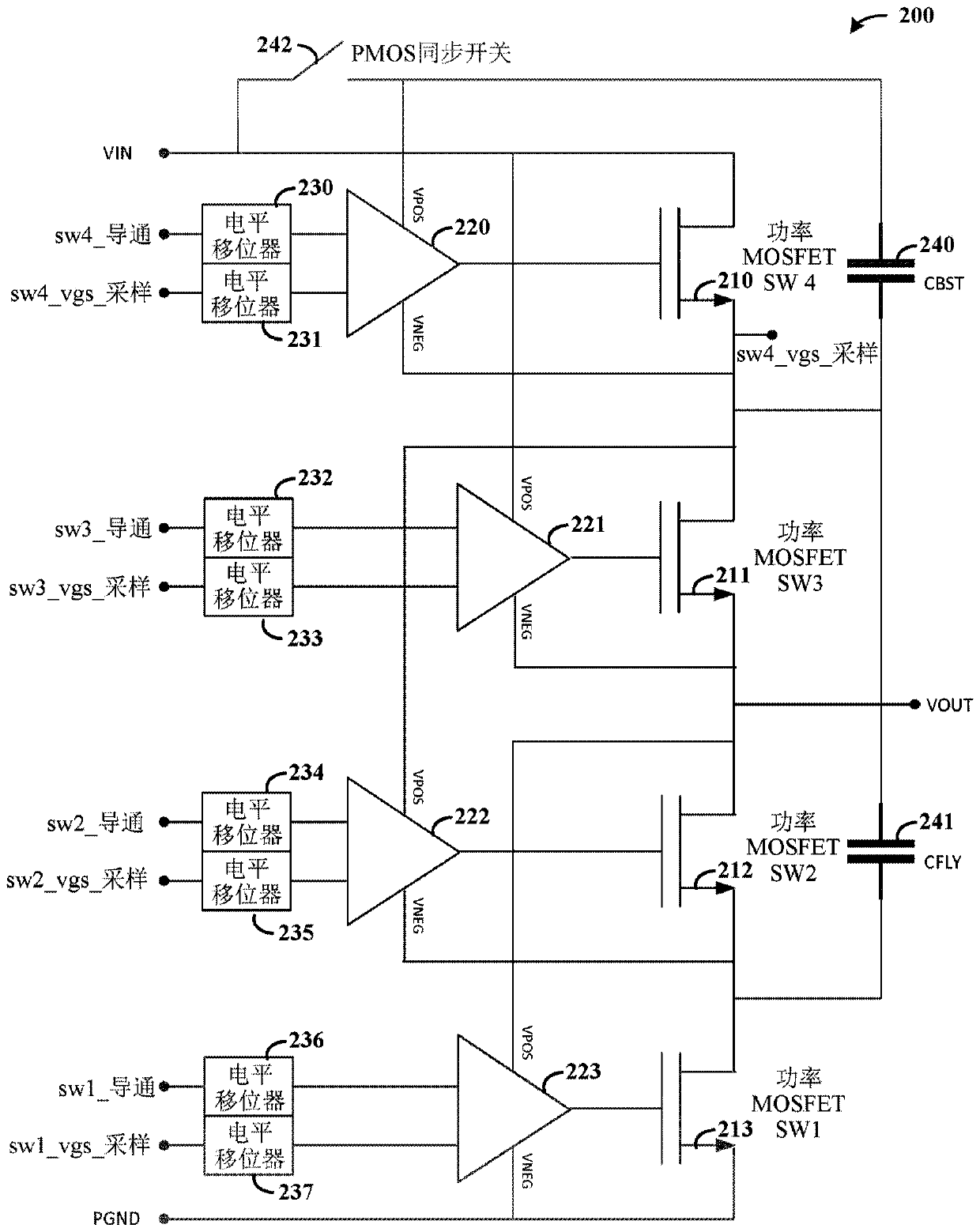
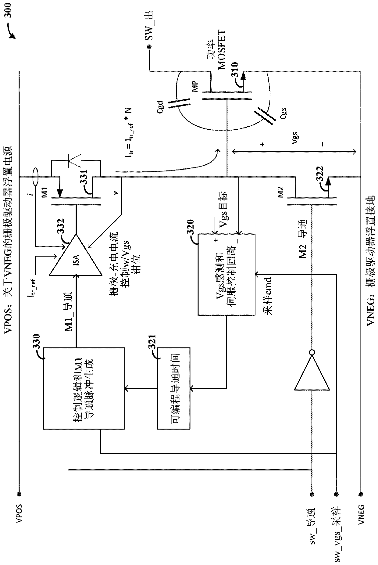
[0015] Aspects of the present disclosure are believed to be applicable to various types of devices, systems and methods involving voltage control, such as for precisely controlling the gate voltage of a transistor. In certain embodiments, aspects of the present disclosure have been shown to be beneficial when used in the context of controlling gate voltage in power MOSFETs and in such applications involving high frequency switching. In some embodiments, gate voltage swing is controlled in power MOSFETs utilized in high switching frequency SCCs. These methods can be implemented with various switched capacitor based power converters using multiple power MOSFETs to deliver charge using switched flying capacitors. While not necessarily so limited, various aspects can be appreciated through the following discussion of non-limiting examples using an illustrative context.

[0016] Various aspects of the present disclosure relate to methods and / or apparatus for addressing the challen...


PUM


Abstract

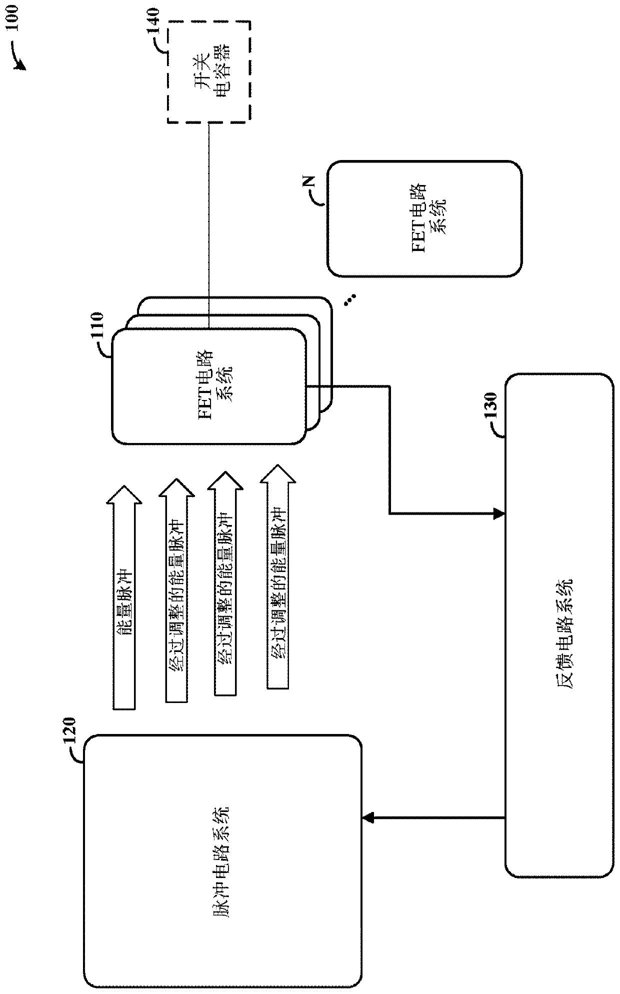
Aspects of the present disclosure relate to a circuit system for controlling a gate voltage. As may be implemented according to one or more embodiments, a voltage level of a field effect transistor (FET) having a floating gate and a target operating voltage is controlled, the FET will be overcharged when above the target operating voltage, and the FET has a nominal operating range when approximately the target operating voltage. A pulse circuit system is configured to apply energy in pulses to the floating gate; in operation, the applied energy pulse is processed to be low relative to a targetoperating voltage of the gate, and then the applied energy is changed by adjusting successive pulses until the gate reaches the target operating voltage. A feedback circuit samples a voltage level ofthe floating gate and enables the pulse circuit system to apply pulse energy to the floating gate to direct operation of the FET based on the target operating voltage within the nominal operating range.

Description

technical field [0001] Aspects of various embodiments relate to voltage control as may be implemented to control gate voltage. Background technique [0002] Voltage control for various applications can be challenging. For example, the gate voltage swing of a transistor such as a power MOSFET in a switched capacitor converter (SCC) can be determined by the supply voltage to the gate driver. This voltage can be derived from the power input pin or an external bootstrap capacitor. Controlling voltage in such applications can be challenging and may require the use of additional circuitry and / or an understanding of what the inefficient control function may be. For example, such a bootstrap voltage source may increase required board area and associated cost, and result in EMI emissions and higher noise levels. For switching applications, the peak current through the power MOSFET during switching can be high, which can cause excessive power supply ringing due to parasitic power s...

Claims


Application Information

Patent Timeline
IPC IPC(8): H03K17/082
CPCH03K17/0822H03K2217/0081H03K17/08122H03K17/162H02M1/08H01L29/788
Inventor 肯尼思·钟·因·夸克赖苏明李学初詹福春卿健
Owner NXP BV
Learn More