Fuel gas thermal desorption-steam enhanced vapor extraction in-situ coupling repair method for composite organic contaminated site

A technology of organic pollution and remediation methods, applied in the restoration of polluted soil and other directions, can solve the problems of true coupling and no mention, and achieve the effect of improving the remediation efficiency and realizing the utilization of waste heat.

Inactive Publication Date: 2020-06-09
BEIJING INSTITUTE OF PETROCHEMICAL TECHNOLOGY
View PDF4 Cites 7 Cited by
  • Summary
  • Abstract
  • Description
  • Claims
  • Application Information

AI Technical Summary

Problems solved by technology

However, there are few literature reports on the coupling of gas thermal desorption and steam-enhanced gas phase extraction, and no one mentions the true coupling between the two.

Method used


Image

  • Fuel gas thermal desorption-steam enhanced vapor extraction in-situ coupling repair method for composite organic contaminated site
  • Fuel gas thermal desorption-steam enhanced vapor extraction in-situ coupling repair method for composite organic contaminated site

Examples


specific Embodiment approach

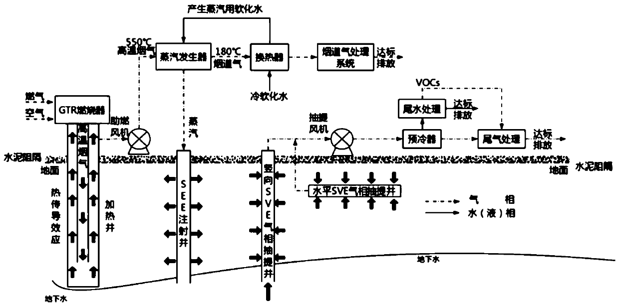
[0011] The gas thermal desorption-steam enhanced gas phase extraction in-situ coupling repair method for complex organic pollution sites of the present invention, its preferred specific implementation is:

[0012] Including high-temperature flue gas heating wells, steam injection wells, and vapor phase extraction wells;

[0013] The high-temperature flue gas produced by the burner conducts heat transfer through the high-temperature flue gas heating well for soil restoration;

[0014] The flue gas returned from the high-temperature flue gas heating well is introduced into the steam generator, and the steam generator is fed with demineralized water for generating steam at the same time, and the heat of the flue gas is used to generate steam and inject it into the steam injection well for steam enhanced gas phase extraction. carry.

[0015] Before coupling restoration, first determine the coupling mode and coupling ratio that adapt to different site characteristics and restorati...

specific Embodiment

[0023] Specific examples, such as figure 1 Shown:

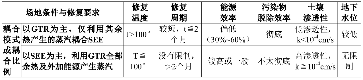
[0024] For complex organic pollution sites of benzene series, petroleum hydrocarbons, polycyclic aromatic hydrocarbons and halogenated hydrocarbons, from the perspectives of remediation temperature, remediation period, energy efficiency, pollutant removal efficiency, low-permeability soil adaptability, and groundwater level adaptability, etc., To couple the respective technical advantages of GTR and SEE, first determine the coupling mode and coupling ratio (the contribution ratio of GTR and SEE to the remediation soil) that adapt to different site characteristics and remediation requirements, as shown in Table 1.

[0025] Table 1 Corresponding matrix of GTR-SEE coupling mode and related parameters

[0026]

[0027] For the GTR-based coupling mode, GTR heating wells, steam injection wells and polluted gas extraction wells are alternately distributed, the depth of various wells and the spacing between wells (including the s...


PUM


Abstract

The invention discloses a fuel gas thermal desorption-steam enhanced vapor extraction in-situ coupling repair method for a composite organic contaminated site. A high-temperature flue gas heating well, a steam injection well and a vapor extraction well are included. High-temperature flue gas generated by a combustor is subjected to heat transfer through the high-temperature flue gas heating well for soil remediation; flue gas returned from the high-temperature flue gas heating well is introduced into the steam generator, softened water for generating steam is introduced into the steam generator at the same time, and steam generated by heat of the flue gas is injected into the steam injection well and used for steam enhanced vapor extraction. High-temperature flue gas generated by thermal desorption of fuel gas and steam generated by external softened water are used for steam injection of steam enhanced vapor extraction, internal coupling of GTR and SEE is truly achieved, waste heat ofhigh-temperature flue gas is recovered, waste heat utilization is achieved, remediation efficiency is greatly improved, and the method is particularly suitable for benzene series, petroleum hydrocarbon, polycyclic aromatic hydrocarbon and halogenated hydrocarbon composite organic contaminated sites.

Description

technical field [0001] The invention relates to an in-situ thermal restoration technology for complex organic pollution sites, in particular to an in-situ coupled repair method for gas thermal desorption-steam enhanced gas phase extraction for complex organic pollution sites. Background technique [0002] The heating temperature of gas thermal desorption repair technology (GTR) is extremely high (700-900°C), which can remove almost all organic pollutants and some volatile inorganic pollutants in situ up to the standard, and is not affected by complex geological and hydrogeological conditions, etc. However, the flue gas emitted by it is as high as 550°C, the energy is wasted, and the energy utilization rate is only 30% to 60%. Moreover, when the removal target area is deep, the heating temperature at the bottom of the ordinary heating well is the highest, and the shallow soil The temperature is low, and it is difficult to reach the target temperature, so it is easy to cause u...

Claims


Application Information

Patent Timeline
Patent Type & Authority Applications(China)
IPC IPC(8): B09C1/06
CPCB09C1/06B09C2101/00
Inventor 桑义敏王飞宇陈家庆朱玲韩严和胡建龙
Owner BEIJING INSTITUTE OF PETROCHEMICAL TECHNOLOGY
Why Eureka
Try Eureka