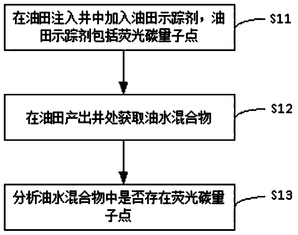
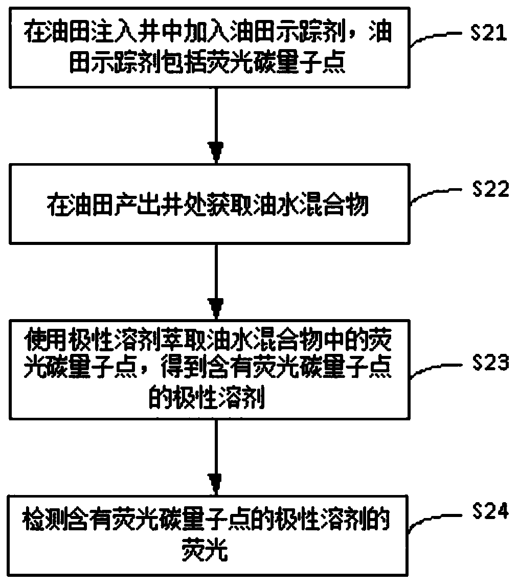
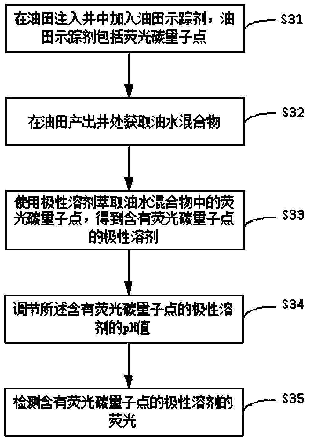
Oil field tracer and oil field tracing method
A tracer and oil field technology, applied in the field of oil field analysis, can solve the problems of high cost, easy adsorption by rocks, unfavorable large-scale popularization and application, etc., and achieve the effects of easy detection, environmental friendliness, and excellent environmental stability.
- Summary
- Abstract
- Description
- Claims
- Application Information
AI Technical Summary
Problems solved by technology
Method used
Image
Examples
Embodiment 1
[0085] The preparation method of fluorescent carbon quantum dot in embodiment 1 is as follows:
[0086] Put 1g of 3,4,9,10-tetranitroperylene in a 500ml beaker, add 200ml of ethanol, 3g of NaOH and 1g of sodium citrate, and ultrasonically dissolve to obtain a mixed solution. Afterwards, the mixed solution was poured into a 300ml stainless steel hydrothermal reaction kettle with a polytetrafluoroethylene liner, reacted at 200°C for 12 hours, and separated and purified to obtain fluorescent carbon quantum dots to be functionalized with amino groups.
[0087] Then carry out amino modification on the surface of the fluorescent carbon quantum dots to be amino-functionalized: in a 250ml three-necked flask, mix 1g of the above-mentioned fluorescent carbon quantum dots to be amino-functionalized, 100ml of ammonia, and 2g of sodium bisulfate. Then it was poured into a 300ml stainless steel hydrothermal reaction kettle with polytetrafluoroethylene lining, and reacted at 200°C for 12 hou...
Embodiment 2
[0090] The preparation method of fluorescent carbon quantum dot in embodiment 2 is as follows:
[0091] Put 1g of 3,4,9,10-tetranitroperylene in a 500ml beaker, add 200ml of ethanol, 3g of NaOH and 1g of sodium citrate, and ultrasonically dissolve to obtain a mixed solution. Afterwards, the mixed solution was poured into a 300ml stainless steel hydrothermal reaction kettle with a polytetrafluoroethylene liner, reacted at 200°C for 12 hours, and separated and purified to obtain fluorescent carbon quantum dots to be functionalized with amino groups.
[0092] Then carry out amino modification on the surface of the fluorescent carbon quantum dots to be amino-functionalized: in a 250ml three-necked flask, mix 1g of the above-mentioned fluorescent carbon quantum dots to be amino-functionalized, 100ml of ammonia, and 2g of sodium bisulfate. Then it was poured into a 300ml stainless steel hydrothermal reaction kettle with polytetrafluoroethylene lining, and reacted at 200°C for 12 hou...
Embodiment 3
[0095] The preparation method of fluorescent carbon quantum dot in embodiment 3 is as follows:
[0096] After placing 1 g of citric acid, 2 ml of polyethylene glycol and 20 ml of deionized water in a 50 ml hydrothermal reaction kettle, they were reacted at 180° C. for 12 hours to obtain the final fluorescent carbon quantum dots. The obtained fluorescent carbon quantum dots can be dispersed in water phase or oil phase.
[0097] The mode of using fluorescent carbon quantum dots in the embodiment 3 for oil field tracing is as follows:
[0098] Take a blank petroleum sample (an oil-water mixture containing water and oil), and after adding the fluorescent carbon quantum dots in Example 3 (simulating the oil-water mixture to be detected in the production well), take an appropriate amount of the above-mentioned fluorescent carbon quantum dots. After pointing the petroleum sample, add 10 ml of ethanol solution, followed by excess sodium hydroxide (NaOH) and 3 ml of ammonia water. Af...
PUM
 Abstract
Description
Claims
Application Information
 - R&D
- Intellectual Property
- Life Sciences
- Materials
- Tech Scout
- Unparalleled Data Quality
- Higher Quality Content
- 60% Fewer Hallucinations
Browse by: Latest US Patents, China's latest patents, Technical Efficacy Thesaurus, Application Domain, Technology Topic, Popular Technical Reports.
© 2025 PatSnap. All rights reserved.Legal|Privacy policy|Modern Slavery Act Transparency Statement|Sitemap|About US| Contact US: help@patsnap.com


