Packaged perovskite solar cell and packaging method

A technology of solar cells and packaging methods, applied in circuits, electrical components, photovoltaic power generation, etc., can solve the problems of perovskite decomposition, perovskite layer decomposition, perovskite material destruction, etc., to improve stability and reduce attenuation. Effect

Pending Publication Date: 2020-06-09
SHANGHAI INST OF CERAMIC CHEM & TECH CHINESE ACAD OF SCI +2
View PDF2 Cites 2 Cited by
  • Summary
  • Abstract
  • Description
  • Claims
  • Application Information

AI Technical Summary

Problems solved by technology

The filling material is usually vacuum-heated and cured for encapsulation, but during the heating process, the perovskite layer may decompose due to the high temperature
In addition, for packaged perovskite batteries, in order to lead out the positive and negative electrodes of the battery for testing or connecting loads, the positive and negative electrodes of the battery are usually drawn out from the edges of the four-sided sealant or by punching holes on the upper and lower cover plates, for example, patent documents In 1, the lead-out ends of the positive and negative electrodes are in contact with the edge encapsulant, and the gap caused by the contact part may induce the entry of water and oxygen; The tape may move during the lamination process to introduce water and oxygen, and after packaging, water and oxygen may still enter the inside of the packaged battery along the metal conduction tape, causing damage to the perovskite material; in Patent Document 2, the conductive ribbons are separated Lead the positive and negative electrodes of the perovskite solar cell module to the hole area of ​​the back plate. Additional packaging is required for the hole area of ​​the back plate, which may cause water vapor to enter due to unsatisfactory packaging effect and cause perovskite decomposition.

Method used


Image

  • Packaged perovskite solar cell and packaging method
  • Packaged perovskite solar cell and packaging method
  • Packaged perovskite solar cell and packaging method

Examples


Embodiment 1

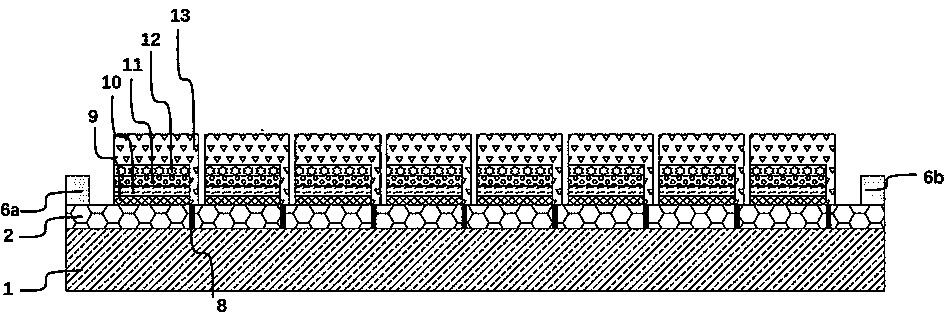
[0071] MAPbI 3 The packaging of perovskite solar cell modules is an example. Among them, the perovskite solar cell module 3 includes 8 perovskite solar cell units, each unit includes an FTO layer (transparent conductive layer 2), a hole blocking layer 9, an electron transport layer 10, a MAPbI 3 Perovskite layer (perovskite light-absorbing layer 11), hole transport layer 12, carbon counter electrode layer (counter electrode layer 13), wherein, MAPbI 3 The perovskite layer is arranged between the electron transport layer and the carbon counter electrode layer; the FTO layers of adjacent battery cells are separated by etching lines 8, and the counter electrode layers are connected to the FTO layers of adjacent unit cells across the etching lines to realize 8 battery cells connected in series.

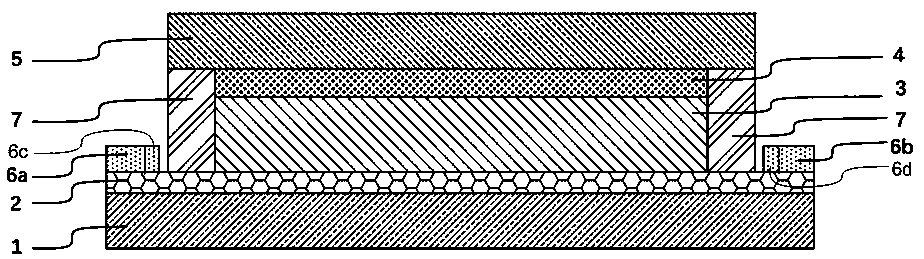
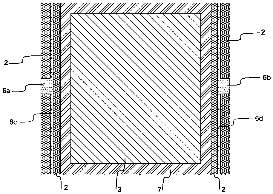
[0072] Such as figure 1 , figure 2 with image 3 As shown, this embodiment relates to a packaged perovskite solar cell module, the front of the cell module is a transparent substrat...

Embodiment 2

[0090] This embodiment provides a perovskite solar cell unit structure different from that of Embodiment 1, such as Figure 4 As shown, it includes a hole blocking layer 9, an electron transport layer 10 located on the upper surface of the hole blocking layer 9, an insulating layer 14 located on the upper surface of the electron transport layer 10, and a perovskite light absorbing layer located on the upper surface of the insulating layer 14. Layer 11, a counter electrode layer 13 located on the upper surface of the perovskite light-absorbing layer 11, wherein the counter electrode layer 13 also covers one side of the perovskite solar cell unit. Since the perovskite light-absorbing layer 11 can transport both holes and electrons, in order to prevent the holes in the perovskite light-absorbing layer 11 from being transferred to the electron-transporting layer 10, an insulating layer 14 needs to be added to block hole transport. Wherein, the perovskite precursor solution penetra...

Embodiment 3

[0104] This example utilizes CsPbI 2 Br perovskite layer (perovskite light-absorbing layer) replaces MAPbI in Example 1 3 The perovskite layer, and the set temperature of the laminator was changed to 150° C., and the rest of the structure and packaging steps were the same as in Embodiment 1, and will not be repeated here.

[0105] Table 5 shows the perovskite solar cells before and after lamination packaging in this embodiment at AM1.5, 100mW / cm 2 The photoelectric conversion parameters measured under the light source.

[0106] The perovskite solar cell performance parameters (AM1.5, 100mW / cm 2 )

[0107]

[0108] Among them, Voc is the open circuit voltage, Jsc is the short circuit current, FF is the fill factor, and Eff is the photoelectric conversion efficiency.

[0109] The packaging method of the present invention is used to package the above-mentioned battery. After packaging, the efficiency of the battery does not decrease, but is slightly improved. It proves tha...


PUM

PropertyMeasurementUnit
Thicknessaaaaaaaaaa
Thicknessaaaaaaaaaa
Thicknessaaaaaaaaaa

Abstract

The invention provides a packaged perovskite solar cell and a packaging method. The solar cell comprises a transparent conductive substrate, a perovskite solar cell module, a packaging adhesive, a cover plate and a total electrode, wherein the perovskite solar cell module is located on the transparent conductive substrate; the packaging adhesive is arranged on the transparent conductive substrateand forms a packaging space to accommodate the perovskite solar cell module; the edge of the cover plate is connected with the top of the packaging adhesive in a sealing manner so as to enable the perovskite solar cell module to be sealed in the packaging space; the total electrode is arranged on the transparent conductive substrate and completely located outside the packaging space, and electronsare transmitted to the total electrode through the transparent conductive substrate. According to the invention, the total electrode is independently arranged outside the packaging adhesive, and thecharacteristic that the transparent conductive substrate can conduct electricity and transmit electrons is utilized, so that the problem that water and oxygen enter the packaging space through the gapdue to the contact between the packaging adhesive and an electrode leading-out part is avoided, and the transmission of the electrons is not influenced.

Description

technical field [0001] The invention relates to the field of photovoltaic technology, in particular to a packaged perovskite solar cell and a package method. Background technique [0002] Perovskite solar cells use organic-inorganic hybrid perovskite materials as the light-absorbing layer, which has excellent characteristics such as continuously adjustable band gap, high light absorption coefficient, long carrier diffusion distance, and simple preparation method, making it a Ideal light-absorbing materials for next-generation photovoltaic devices. Since the invention of titanium ore solar cells in 2009, the efficiency has continuously broken through, and the current highest certified efficiency is 25.2%. However, the commercial application of perovskite batteries still needs to solve technical problems such as large-scale large-scale preparation and improvement of long-term environmental stability. Perovskite solar cells are exposed to the air for a long time, and their st...

Claims


Application Information

Patent Timeline
IPC IPC(8): H01L51/44H01L51/48
CPCH10K30/80H10K30/81H10K30/88Y02E10/549
Inventor 杨松旺陈薪羽邬荣敏陈宗琦寿春晖沈曲丁莞尔洪凌俞丹馨季志江王美树
Owner SHANGHAI INST OF CERAMIC CHEM & TECH CHINESE ACAD OF SCI
Why Eureka
Try Eureka