
Coupling identification and decoupling control design method of two-degree-of-freedom servo cradle head system

A technology of decoupling control and design method, which is applied in the field of coupling identification and decoupling control design, and can solve problems such as huge amount of calculation, inability to design frequency domain characteristics, and occupying large computing resources.

Inactive Publication Date: 2020-06-12
SOUTH CHINA UNIV OF TECH
View PDF1 Cites 4 Cited by
  • Summary
  • Abstract
  • Description
  • Claims
  • Application Information

AI Technical Summary

Problems solved by technology

Intelligent linearization decoupling control methods do not depend on the dynamic model of the system, mainly including neural network decoupling, least squares support vector machine, fuzzy decoupling, etc. The common problem of intelligent linearization decoupling is that the control algorithm is complex The parameterization process is cumbersome and requires a lot of computing resources; the state feedback linear decoupling is simpler than the intelligent decoupling, and is widely used in the decoupling control of complex nonlinear systems, which can be mainly divided into dynamic inverse system decoupling and differential geometric solution Coupling, dynamic inverse system decoupling requires the system to be reversible, while differential geometric decoupling needs to ensure that the system can be transformed into an affine transformation model
The method of compensation decoupling control is mainly based on the precise mathematical model of the system. The coupling model is calculated or identified, and then feedback or feedforward compensation control is performed. design, the final control effect often has a great relationship with the identified model parameters, and the model parameters largely determine the quality of the control effect
[0004] For the decoupling control design of the two-degree-of-freedom servo pan / tilt system, the controller is mainly implemented by an embedded single-chip microcomputer, which requires high real-time performance. In order to ensure an effective control effect within the control cycle, the control method, such as an intelligent algorithm, requires too much calculation. , the design needs repeated parameter adjustment and training, and it is often difficult to play a role in the servo system with high real-time requirements
For the decoupling method of state feedback, the design process is more complicated, and it cannot be designed for the frequency domain characteristics, which is not conducive to the analysis of the performance of each frequency band of the system

Method used


Image

  • Coupling identification and decoupling control design method of two-degree-of-freedom servo cradle head system
  • Coupling identification and decoupling control design method of two-degree-of-freedom servo cradle head system
  • Coupling identification and decoupling control design method of two-degree-of-freedom servo cradle head system

Examples


Embodiment 1

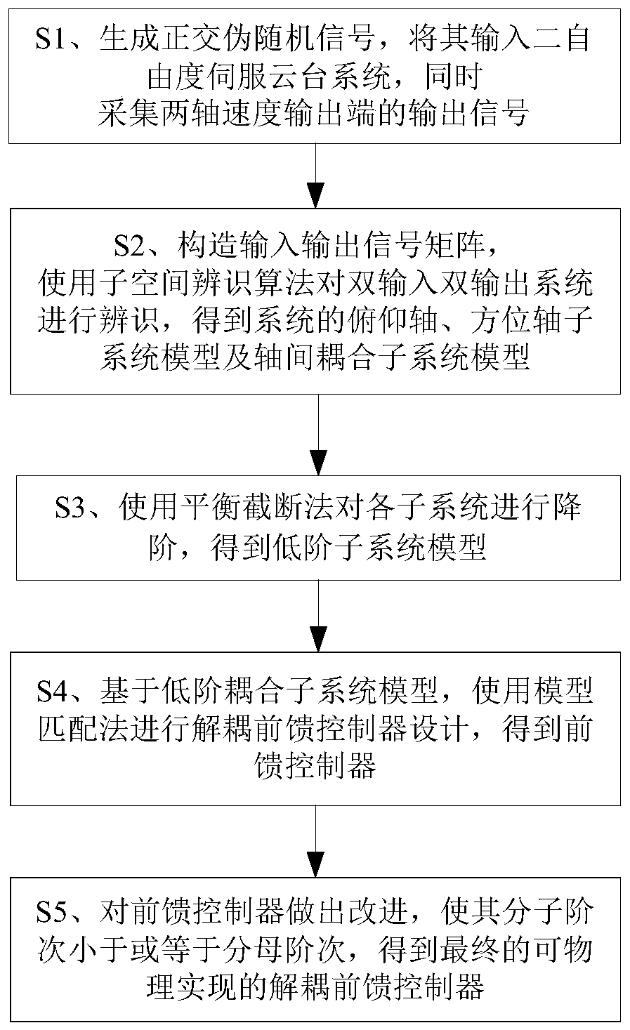
[0076] This embodiment discloses a coupling identification and decoupling control design method for a two-degree-of-freedom servo pan / tilt system, as shown in figure 1 As shown, the steps are as follows:

[0077] S1. Generate an orthogonal pseudo-random signal, input it into the two-degree-of-freedom servo pan-tilt system, and simultaneously collect output signals from two-axis speed output terminals.

[0078] Currently, the input signals used for system identification are usually white noise signals and pseudo-random signals. Relatively speaking, the random characteristics of white noise signals easily lead to statistical errors, while the low-frequency autocorrelation function of pseudo-random signals is similar to white noise and is easy to generate. Therefore, in this embodiment, a pseudo-random signal is used as an input signal for system identification. Considering that the two-degree-of-freedom servo pan-tilt system is a dual-input and dual-output system, it is difficu...

Embodiment 2

[0132] This embodiment discloses a storage medium, which stores a program. When the program is executed by a processor, the coupling identification and decoupling control design method of the two-degree-of-freedom servo pan / tilt system described in Embodiment 1 is implemented, specifically as follows:

[0133] S1. Generate an orthogonal pseudo-random signal, input it into the two-degree-of-freedom servo pan-tilt system, and collect the output signals of the two-axis speed output terminals at the same time;

[0134] S2. Construct the input-output signal matrix, use the subspace identification algorithm to identify the double-input and double-output system, and obtain the system's pitch axis, azimuth axis subsystem model and inter-axis coupling subsystem model;

[0135] S3. Using the balanced truncation method to reduce the order of each subsystem to obtain a low-order subsystem model;

[0136] S4. Based on the low-order coupled subsystem model, use the model matching method to ...

Embodiment 3

[0140] This embodiment discloses a computing device, including a processor and a memory for storing executable programs of the processor. When the processor executes the program stored in the memory, the two-degree-of-freedom servo pan-tilt system described in Embodiment 1 is realized. The coupling identification and decoupling control design methods of the system are as follows:

[0141] S1. Generate an orthogonal pseudo-random signal, input it into the two-degree-of-freedom servo pan-tilt system, and collect the output signals of the two-axis speed output terminals at the same time;

[0142] S2. Construct the input-output signal matrix, use the subspace identification algorithm to identify the double-input and double-output system, and obtain the system's pitch axis, azimuth axis subsystem model and inter-axis coupling subsystem model;

[0143] S3. Using the balanced truncation method to reduce the order of each subsystem to obtain a low-order subsystem model;

[0144] S4. ...


PUM


Abstract

The invention discloses a coupling identification and decoupling control design method for a two-degree-of-freedom servo holder system, and the method comprises the steps: firstly generating an orthogonal pseudo-random signal, inputting the orthogonal pseudo-random signal into the two-degree-of-freedom servo holder system, and collecting an output signal of a two-axis speed output end; constructing an input and output signal matrix, and identifying the two-input and two-output system by using a subspace identification algorithm to obtain a pitch axis subsystem model, an azimuth axis subsystemmodel and an inter-axis coupling subsystem model of the system; performing order reduction on each subsystem by using a balanced truncation method to obtain a low-order subsystem model; based on the low-order coupling subsystem model, carrying out decoupling feedforward controller design by using a model matching method to obtain a feedforward controller; and finally, improving the feedforward controller, so as to enable the molecular order of the feedforward controller to be smaller than or equal to the denominator order, and obtaining the final physically-achievable decoupling feedforward controller. According to the invention, the vibration of the pitch axis of the two-degree-of-freedom servo pan-tilt system caused by inter-axis coupling can be effectively suppressed.

Description

technical field [0001] The invention relates to the technical field of servo system control, in particular to a coupling identification and decoupling control design method for a two-degree-of-freedom servo pan-tilt system. Background technique [0002] For the servo pan / tilt system, because there are many flexible modes and nonlinear structures in its structure, there are multiple resonance frequency points in the system, and the two-degree-of-freedom servo pan / tilt system is more likely to cause inter-axis coupling and increase system complexity. sex. For some servo pan / tilt control designs that require high-precision performance, often due to the existence of coupling, when the pan / tilt moves on two axes, the movement of one axis will have an impact on the vibration of the other axis, which is not conducive to the servo pan / tilt system. High precision control design. [0003] Aiming at the problem of decoupling control of multivariable coupled systems, there are current...

Claims


Application Information

Patent Timeline
IPC IPC(8): G05B13/04G05D3/10
CPCG05B13/042G05D3/10
Inventor 陈燕坤苏为洲谭敏哲闻成
Owner SOUTH CHINA UNIV OF TECH
Learn More