
Instantaneous frequency measurement method and system with adjustable measurement range based on polarization modulator

A technology of measurement range and instantaneous frequency, which is applied in the field of instantaneous frequency measurement and system with adjustable measurement range based on polarization modulator, can solve the problems that the system cannot perform instantaneous measurement, the slope of ACF function is small, and the measurement resolution is low. Simple structure, improved resolution, and low system cost

Inactive Publication Date: 2020-06-12
BEIJING UNIV OF POSTS & TELECOMM
View PDF19 Cites 7 Cited by
  • Summary
  • Abstract
  • Description
  • Claims
  • Application Information

AI Technical Summary

Problems solved by technology

However, the use of dual lasers will increase the cost of the system; the measurement range can also be adjusted by adjusting the wavelength of the laser or the dispersion of the dispersive element, but it needs to be recalibrated to ensure the measurement accuracy, and the system cannot perform instantaneous measurement; in addition, it can be based on dual polarization Mach Zehnder modulator (DPol-MZM) to achieve adjustable measurement range, but the system requires complex bias control to minimize the bias drift of the MZM
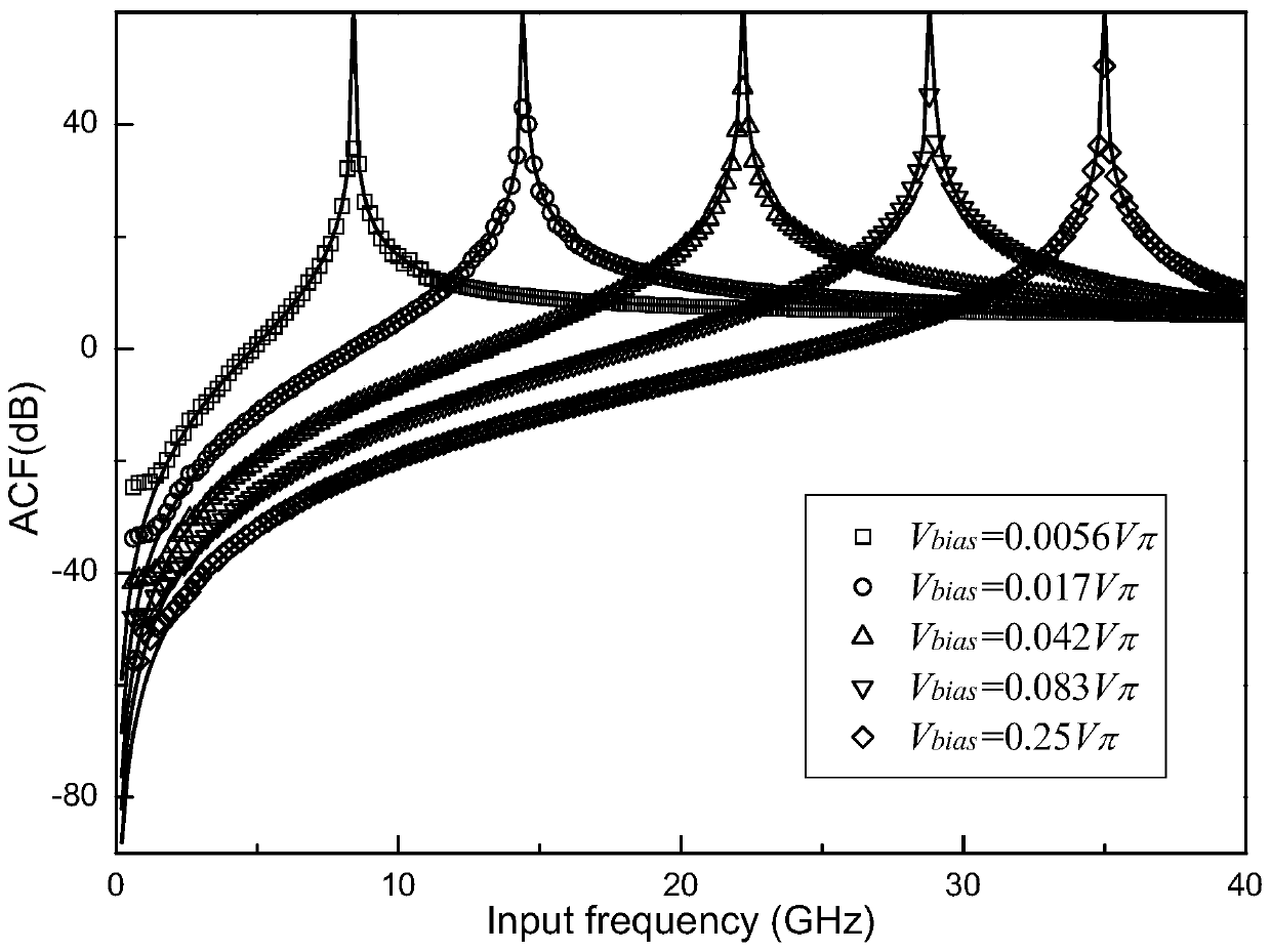
The microwave power monitoring system based on two wavelengths performs well in terms of range adjustability, but its significant defect is that the slope of the ACF function is small, resulting in low measurement resolution

Method used


Image

  • Instantaneous frequency measurement method and system with adjustable measurement range based on polarization modulator
  • Instantaneous frequency measurement method and system with adjustable measurement range based on polarization modulator
  • Instantaneous frequency measurement method and system with adjustable measurement range based on polarization modulator

Examples


Embodiment Construction

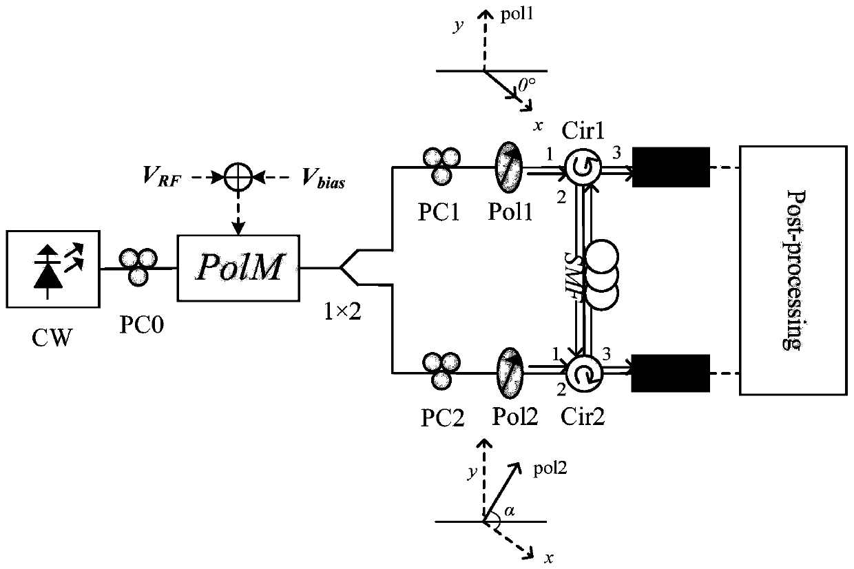
[0041] The present invention provides a method and system for realizing microwave instantaneous frequency measurement. The system links are as follows: figure 1 As shown, the specific implementation needs to adopt the following steps:

[0042] The linearly polarized light emitted by the continuous wave laser with a center wavelength of 1550nm and a linewidth of 0.5MHz is injected into the optical polarization modulator PolM through the polarization controller PC0, and PC0 is adjusted to make the polarization direction of the linearly polarized light consistent with that of the TE mode and TM mode of PolM The polarization directions are all at an angle of 45°, so that the components of linearly polarized light on the two orthogonal polarization states of PolM are equal; the microwave signal to be measured with unknown frequency and a DC bias voltage V bias Coupling drives PolM to perform phase modulation with equal modulation coefficients and opposite signs to TE mode and TM mo...


PUM


Abstract

The invention provides an instantaneous frequency measurement method and system with an adjustable measurement range based on a polarization modulator, and relates to the field of microwave photonics.In the system, TE and TM modes of light waves are subjected to constant-amplitude reverse-phase modulation through a light polarization modulator, and relative phase shift is introduced between the TE and TM modes through bias voltage; combining TE mode light waves and TM mode light waves through an optical power divider shunt and a polarizing film; further introducing equivalent dispersion intoupper and lower paths through a dispersion module formed by optical fibers; mapping the frequency information of a to-be-measured signal to phase information caused by dispersion, carrying out the photoelectric conversion through PD, transferring the frequency information to the amplitude of a photocurrent alternating current component, constructing an amplitude comparison function ACF through thealternating current component in a photocircuit, and calculating the frequency of the to-be-measured signal through the ACF function. The system is simple in structure, the measurement range of the system can be changed by adjusting the bias voltage and the polarization angle of the lower branch, and the measurement resolution of the system can be improved by optimizing the slope of the ACF.

Description

technical field [0001] The invention relates to the field of optical communication and the field of microwave photonics measurement technology, in particular to the frequency-amplitude mapping frequency measurement technology that converts the frequency information of microwave signals into power information through the dispersion effect. The instantaneous frequency measurement method and system that can change the measurement range of the system and improve the measurement resolution of the system by optimizing the slope of the ACF and the polarization angle of the lower branch. Background technique [0002] In the field of electronic warfare (EW), instantaneous microwave frequency measurements (IFM) of received radar signals can be used to identify unknown radio frequencies (RF) before further processing. Due to its inherent electrical bottleneck, conventional electronic frequency monitors have a limited measurement range, centered at 0.5 to 18GHz, and perform poorly in co...

Claims


Application Information

Patent Timeline
IPC IPC(8): H04B10/079
CPCH04B10/0795
Inventor 马健新郭艳婷
Owner BEIJING UNIV OF POSTS & TELECOMM
Learn More