Novel ship tail gas treatment system

A technology for ship exhaust and treatment systems, which is applied in the fields of dispersed particle separation, chemical instruments and methods, separation methods, etc., can solve problems such as the inability of engine exhaust emissions, and achieves reduction of greenhouse gas effects, volume reduction, and uniform diffusion. Effect

Active Publication Date: 2020-06-26
DALIAN SHIPBUILDING IND
View PDF6 Cites 5 Cited by
  • Summary
  • Abstract
  • Description
  • Claims
  • Application Information

AI Technical Summary

Problems solved by technology

However, this treatment method requires an additional set of urea storage, injection, cleaning, soot blowing and other systems. At the same time, the tail gas after the reaction is mixed with CO2 because urea is used as a reducing agent. The exhaust emission of this engine cannot be achieved. "Zero Carbon" Emissions

Method used


Image

  • Novel ship tail gas treatment system
  • Novel ship tail gas treatment system
  • Novel ship tail gas treatment system

Examples


Embodiment 1

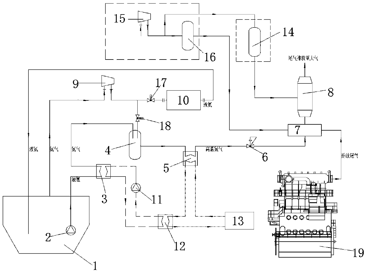
[0027] Such as figure 2As shown, when there is too much volatilized ammonia in the liquid ammonia fuel storage tank and the tail gas treatment requires less ammonia, open the first valve and the second valve to run the ammonia liquefaction system. The liquid ammonia low-pressure pump does not work, and the volatilized ammonia gas in the liquid ammonia fuel storage tank enters the ammonia gas compressor for compression. After compression, part of the ammonia gas enters the ammonia gas buffer tank through the second valve, and the other part of the ammonia gas enters through the first valve. Ammonia liquefaction device, liquefied to form liquid ammonia, and returned to the liquid ammonia fuel storage tank.

[0028] The compressed ammonia gas enters the ammonia gas buffer tank for buffering, and then enters the ammonia gas heater to be heated to form high-temperature ammonia gas. After the control system controls the flow regulating valve to adjust the flow of ammonia gas, it is...

Embodiment 2

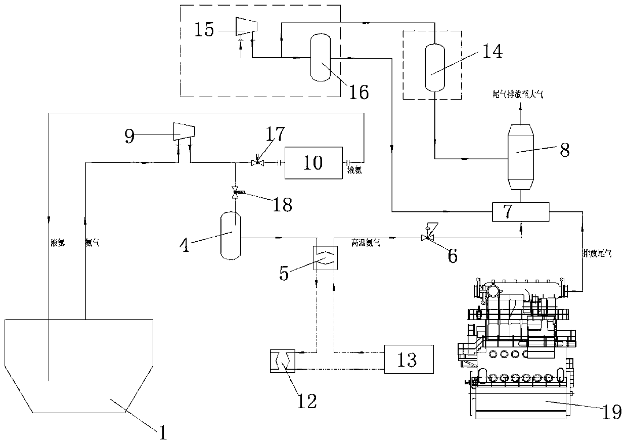
[0032] Such as image 3 As shown, when the volatilized ammonia gas in the liquid ammonia fuel storage tank is basically equal to the amount of ammonia gas required for tail gas treatment, the second valve is opened, the first valve is closed, and the ammonia liquefaction system is stopped. The liquid ammonia low-pressure pump does not work, and the volatilized ammonia gas in the liquid ammonia fuel storage tank enters the ammonia gas compressor for compression. After compression, part of the ammonia gas enters the ammonia gas buffer tank through the second valve, and the other part of the ammonia gas enters through the first valve. Ammonia liquefaction device, liquefied to form liquid ammonia, and returned to the liquid ammonia fuel storage tank.

[0033] The compressed ammonia gas enters the ammonia gas buffer tank for buffering, and then enters the ammonia gas heater to be heated to form high-temperature ammonia gas. After the control system controls the flow regulating valv...

Embodiment 3

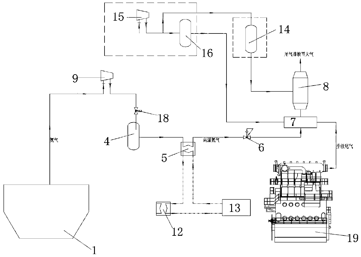
[0036] Such as Figure 4 As shown, when there is too little volatilized ammonia in the liquid ammonia fuel storage tank and the amount of ammonia required for tail gas treatment is too much, the second valve is opened, and the ammonia liquefaction system does not operate. There is low-temperature liquid ammonia (-33.6°C) stored in the liquid ammonia fuel storage tank, and the liquid ammonia low-pressure pump pressurizes the liquid ammonia in the liquid ammonia fuel storage tank to 18bar, and the liquid ammonia in the liquid ammonia fuel storage tank is supplied by the liquid ammonia low-pressure pump It is pumped out and evaporated in the liquid ammonia evaporator to form low-temperature ammonia gas. The low-temperature ammonia gas enters the ammonia gas buffer tank for buffering, and then enters the ammonia gas heater to be heated to form high-temperature ammonia gas. The ammonia gas is adjusted by the control system to control the flow regulating valve. After the flow rate, ...


PUM


Abstract

A novel ship tail gas treatment system is provided with an air compression system and a soot blower, the air compression system is connected with a flue gas mixer, the flue gas mixer is connected withan SCR reactor, the soot blower is connected with the SCR reactor, tail gas exhausted by a fuel main engine enters the flue gas mixer, and the flue gas mixer is connected with an ammonia gas conveying system. The ammonia gas conveying system is provided with a liquid ammonia fuel storage tank and an ammonia gas liquefaction device, a liquid ammonia low-pressure pump is arranged in the liquid ammonia fuel storage tank, and liquid ammonia is pumped out through the liquid ammonia low-pressure pump and finally enters the flue gas mixer. Volatile gas in the liquid ammonia fuel storage tank is fully utilized, the method is preferentially applied to ammonia fuel main engine tail gas denitrification treatment, and the ammonia gas liquefaction device is arranged as a supplement means for ammonia volatile gas treatment, so that the volatile gas in the liquid ammonia storage tank can be completely treated, the pressure rise and structural damage of the liquid ammonia storage tank caused by continuous accumulation of the ammonia volatile gas are avoided, a large amount of the ammonia volatile gas is prevented from being discharged to the atmosphere, and the safety of the liquid ammonia storage tank and a ship is guaranteed.

Description

technical field [0001] The invention relates to the fields of ship construction and ship design, in particular to a novel ship tail gas treatment system. Background technique [0002] The current global warming phenomenon is intensifying, leading to frequent occurrence of extreme weather phenomena and natural disasters around the world. The main culprit is the emission of greenhouse gases represented by CO2. In the field of shipping, the IMO International Maritime Organization has also formulated the latest EEDI standard on carbon emissions. As time goes by, this standard puts forward higher requirements for ship design, ship supporting equipment, and new energy technology applications. [0003] Exhaust gas from diesel engines and low-speed ammonia-fueled engines contains nitrogen oxides such as NO and NO2, which do not meet the IMO tierIII emission standards for nitrogen oxides. In view of this situation, the traditional method is to add an additional set of SCR reactors fo...

Claims


Application Information

Patent Timeline
Patent Type & Authority Applications(China)
IPC IPC(8): B01D53/94B01D53/56
CPCB01D53/9418B01D53/9431B01D2251/2062
Inventor 片成荣张义明吕志勇何旭彭贵胜嵇智勇李达孙强吴楠吕岩杜欣孙凯强马俊张艳丽贾淑洁张梅张晖
Owner DALIAN SHIPBUILDING IND
Why Eureka
Try Eureka