Heat pump self-breathing type drying device and drying control method thereof
A self-breathing, drying device technology, applied in the direction of drying gas arrangement, drying solid materials, local stirring dryer, etc., can solve the problems of increased energy consumption, humidity control medium temperature, humidity reduction, large energy consumption, etc. Drying energy consumption, realizing recycling, and the effect of safe treatment process
- Summary
- Abstract
- Description
- Claims
- Application Information
AI Technical Summary
Problems solved by technology
Method used
Image
Examples
Embodiment 1
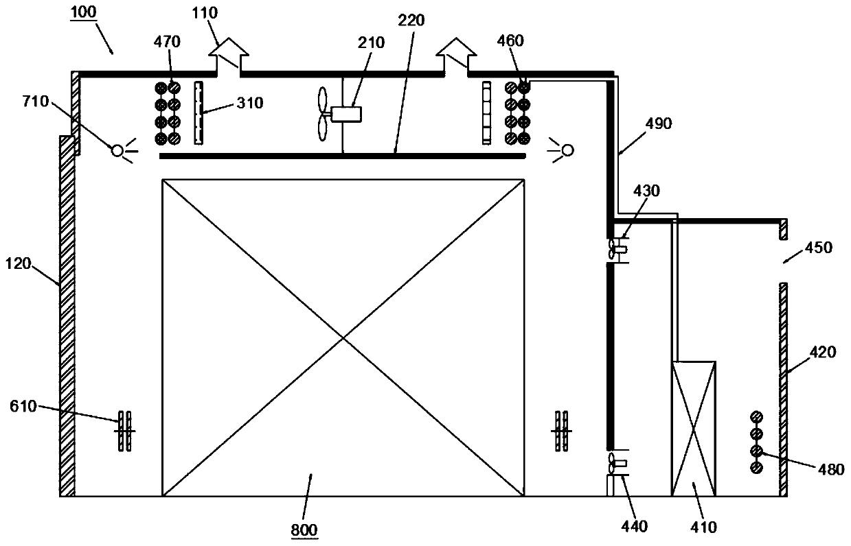
[0038] Example 1: Reference figure 1 A heat pump self-breathing drying device shown includes a drying kiln 100, a gas circulation system, a condensation drainage system, a heating system, a humidification system, and a control system. The drying kiln 100 can be any drying kiln in the prior art that can be used for drying or water balance treatment of wood, fruit, crops (such as peanuts, etc.), such as a kiln body that includes a brick structure or an aluminum alloy structure, and is opened on the kiln body. A pair of exhaust windows 110 at the top, a kiln door 120 and other basic structures, the exhaust window 110 can be opened and closed by the damper, and the material pile 800 to be processed is placed in the middle of the kiln body space. The gas circulation system can be any structure in the prior art that can be used to realize the circulation of the humidity control medium in the kiln body space, for example, it includes a fan 210 installed on the top wall of the kiln bo...
Embodiment 2
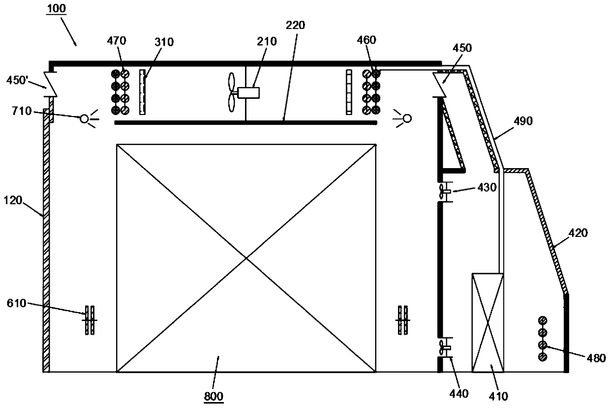
[0059] Embodiment 2: the difference between embodiment 2 and embodiment 1 is that, refer to figure 2 As shown, the heat pump room 420 is a greenhouse-type heat pump room equipped with solar collectors. The solar collector can be any solar collector or lighting glass in the prior art, so that the heat pump 410 can collect solar energy and use it for heating. Preferably, the exhaust windows 110 are symmetrically arranged on the front and rear side walls of the kiln body, and one of the exhaust windows 110 is used as a damper 440 to communicate with the inside of the drying kiln 100 and the heat pump machine room 420, so as to promote the drying process between the drying kiln 100 and the heat pump. The exchange of humidity-regulating medium between the equipment rooms 420 .
[0060] In this embodiment, when the heat pump room 420 is a greenhouse-type heat pump room, solar energy can be used to increase the indoor temperature of the heat pump room 420, that is, to increase the ...
Embodiment 3
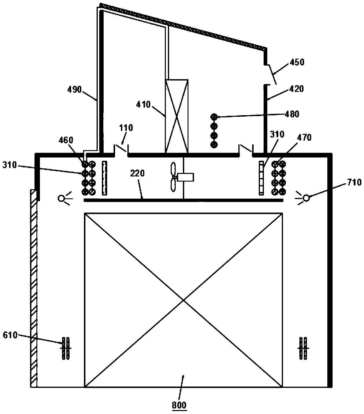
[0061] Embodiment 3: the difference between embodiment 3 and embodiment 1 is that, refer to image 3 As shown, in this embodiment, the heat pump room 420 is set on the top of the drying kiln 100 , and the damper 440 is on one side wall of the heat pump room 420 . Since the heat pump machine room 420 is top-mounted, there is no need to additionally install the first air induction device 430 or the second air induction device 440. The humidity control medium in the drying kiln 100 can enter and leave the heat pump machine room through the exhaust window 110 on the top of the kiln body. 420 and flows through the heat pump 410.
[0062] As a further improvement, the heat pump room 420 is a greenhouse-type heat pump room equipped with solar collectors.
PUM
 Abstract
Description
Claims
Application Information
 - R&D
- Intellectual Property
- Life Sciences
- Materials
- Tech Scout
- Unparalleled Data Quality
- Higher Quality Content
- 60% Fewer Hallucinations
Browse by: Latest US Patents, China's latest patents, Technical Efficacy Thesaurus, Application Domain, Technology Topic, Popular Technical Reports.
© 2025 PatSnap. All rights reserved.Legal|Privacy policy|Modern Slavery Act Transparency Statement|Sitemap|About US| Contact US: help@patsnap.com


