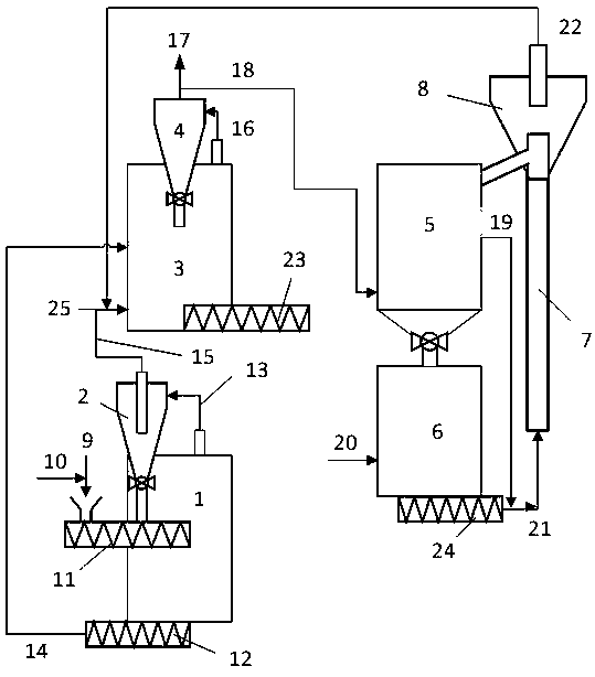
Biomass microwave gasification utilization method and system

A technology of biomass and biomass raw materials, applied in gasification process, manufacture of combustible gas, petroleum industry, etc., can solve problems such as poor quality of synthesis gas and hydrogen

Active Publication Date: 2020-07-07
CHINA PETROLEUM & CHEM CORP +1
View PDF25 Cites 2 Cited by
  • Summary
  • Abstract
  • Description
  • Claims
  • Application Information

AI Technical Summary

Problems solved by technology

[0005] Aiming at the deficiencies in the prior art, the present invention provides a biomass microwave gasification utilization method and system, which can obtain high-purity hydrogen while preparing high-quality synthesis gas, and the obtained synthesis gas can meet the requirements of synthetic liquid fuels. Solve the problem of poor quality of synthesis gas and hydrogen in the process of preparing synthesis gas and hydrogen using biomass as raw material in the prior art, the process economy is significantly improved, and it has a good application prospect

Method used


Image

  • Biomass microwave gasification utilization method and system

Examples


Embodiment 1

[0059] According to the molar ratio of ferric nitrate, nickel nitrate and titanium sulfate 1:1:0.34, weigh 0.625 mol of ferric nitrate, 0.625 mol of nickel nitrate and 0.2125 mol of titanium sulfate to make 1L solutions respectively. In a reaction vessel with 50g of magnesium oxide, under stirring conditions, 3L of urea solution (2mol / L) was mixed dropwise and stirred for 4 hours, and then the ferric nitrate and nickel nitrate solutions were added dropwise in parallel was added, and the co-precipitation reaction was continued for 4 hours. During this process, a precipitate gradually formed. After the reaction was complete, it was centrifuged, and the precipitate was filtered and washed with deionized water to neutrality. The precipitate was dried at 60°C for 12 hours, then burned at 950°C for 8 hours, and obtained after natural cooling. Oxygen carrier A (31wt%Fe 2 o 3 , 29wt%NiO, 10wt%TiO 2 , 30wt%MgO).

Embodiment 2

[0061] According to the molar ratio of ferric nitrate, copper nitrate and zirconium sulfate 1:0.18:0.09, weigh 0.625 mol of ferric nitrate, 0.1125 mol of copper nitrate and 0.05625 mol of zirconium sulfate to make 1L solutions respectively. Contains 20g α-Al 2 o 3In the reaction vessel, under stirring conditions, 3L urea solution (2mol / L) was mixed dropwise and stirred for 4h, and then ferric nitrate and copper nitrate solutions were added dropwise in parallel, and the co-production was continued. The precipitation reaction was 4 hours. During this process, a precipitate gradually formed. After the reaction was complete, it was centrifuged, and the precipitate was filtered and washed with deionized water to neutrality. The precipitate was dried at 60°C for 12 hours, then burned at 950°C for 8 hours, and obtained after natural cooling. Oxygen carrier B (58.2wt%Fe 2 o 3 , 10.5wt%CuO, 8.0wt%ZrO 2 , 23.3wt%Al 2 o 3 ).

Embodiment 3

[0063] According to the molar ratio of ferric nitrate, copper nitrate and titanium sulfate 1:0.4:0.2, weigh 0.625 mol of ferric nitrate, 0.25 mol of copper nitrate and 0.1125 mol of titanium sulfate to make 1L solutions respectively. Contains 20g α-Al 2 o 3 In the reaction vessel, under stirring conditions, 3L urea solution (2mol / L) was mixed dropwise and stirred for 4h, and then ferric nitrate and copper nitrate solutions were added dropwise in parallel, and the co-production was continued. The precipitation reaction was 4 hours. During this process, a precipitate gradually formed. After the reaction was complete, it was centrifuged, and the precipitate was filtered and washed with deionized water to neutrality. The precipitate was dried at 60°C for 12 hours, then burned at 950°C for 8 hours, and obtained after natural cooling. Oxygen carrier C (50.5wt%Fe 2 o 3 , 20.2wt%CuO, 9.1wt%TiO 2 , 20.2wt%Al 2 o 3 ).


PUM

PropertyMeasurementUnit
sizeaaaaaaaaaa

Abstract

The invention discloses biomass microwave gasification utilization method and system, wherein the method comprises the steps: enabling a biomass raw material to enter a microwave pyrolysis reactor fora pyrolysis reaction to obtain a pyrolysis volatile component and a pyrolysis solid-phase material after the reaction, and performing gas-solid separation on the pyrolysis volatile component for obtaining a first gas-phase material and a solid-phase material; feeding the first gas-phase material and the pyrolysis solid-phase material to a microwave gasification reactor, and carrying out gas-solidseparation on a gas-phase product to obtain synthesis gas; feeding the synthesis gas to an oxygen carrier reduction reactor to react with an oxygen carrier in the reactor to obtain a reduction-stateoxygen carrier and a second gas-phase material; feeding the obtained reduction-state oxygen carrier to an oxygen carrier regenerator to be in contact with water vapor for reaction, so that hydrogen and an oxidation-state oxygen carrier are obtained after the reaction. The synthesis gas obtained by the method disclosed by the invention can meet the requirements of synthesis of liquid fuel, and theproblem of poor quality of the synthesis gas and hydrogen in a process for preparing the synthesis gas and the hydrogen by taking biomass as a raw material in the prior art is solved.

Description

technical field [0001] The invention belongs to the technical field of biomass utilization, and relates to a biomass gasification utilization method and system, in particular to a biomass microwave utilization method and system. Background technique [0002] my country is rich in biomass resources, but the utilization methods are backward, and the energy utilization efficiency is low, resulting in a serious waste of biomass resources. Research and development of clean and efficient biomass utilization technology has become one of the important contents to solve the current shortage of petroleum resources, develop biomass energy economy and reduce environmental pollution. Biomass gasification technology can generate gaseous small molecular compounds mainly including hydrogen, carbon monoxide, carbon dioxide and methane. The whole process is relatively clean, and there is no cumbersome separation and purification problem. Hydrogen needed by industry can be obtained by pressur...

Claims


Application Information

Patent Timeline
Patent Type & Authority Applications(China)
IPC IPC(8): C10J3/64C10J3/84
CPCC10J3/64C10J3/84C10J2300/0916C10J2300/092C10J2300/0956C10J2300/0959C10J2300/0969C10J2300/0976C10J2300/0983C10J2300/0996C10J2300/1269C10J2300/1807
Inventor 王鑫宋永一张彪赵丽萍吴斯侃刘继华
Owner CHINA PETROLEUM & CHEM CORP
Why Eureka
Try Eureka