Winding type optical coating device and method based on magnetron sputtering and electron gun evaporation

A magnetron sputtering coating and magnetron sputtering technology, applied in the direction of sputtering coating, vacuum evaporation coating, ion implantation coating, etc. Problems such as weak adhesion

Inactive Publication Date: 2020-07-07
ZHAOQING KERUN VACUUM EQUIP
View PDF0 Cites 6 Cited by
  • Summary
  • Abstract
  • Description
  • Claims
  • Application Information

AI Technical Summary

Problems solved by technology

[0003] (1) The structure of the film layer formed by magnetron sputtering coating process is generally relatively dense, and the bonding force with the substrate is weak, so it is difficult to form a good film layer, which affects the optical properties of the coated product;
[0004] (2) The film forming speed of magnetron sputtering coating is relatively slow, so it is difficult to form a thicker film layer on the surface of the substrate, and the coating effect is difficult to achieve an ideal state;
[0005] (3) In the silicon oxide film layer, there are often parts of silicon oxide with weak adhesion, which are easy to attach to the surface of the film layer in a free state, which affects the cleanliness of the product after coating, and also reduces the transparency of the film layer, thereby Affect the optical properties of the film layer

Method used


Image

  • Winding type optical coating device and method based on magnetron sputtering and electron gun evaporation
  • Winding type optical coating device and method based on magnetron sputtering and electron gun evaporation
  • Winding type optical coating device and method based on magnetron sputtering and electron gun evaporation

Examples


Embodiment 1

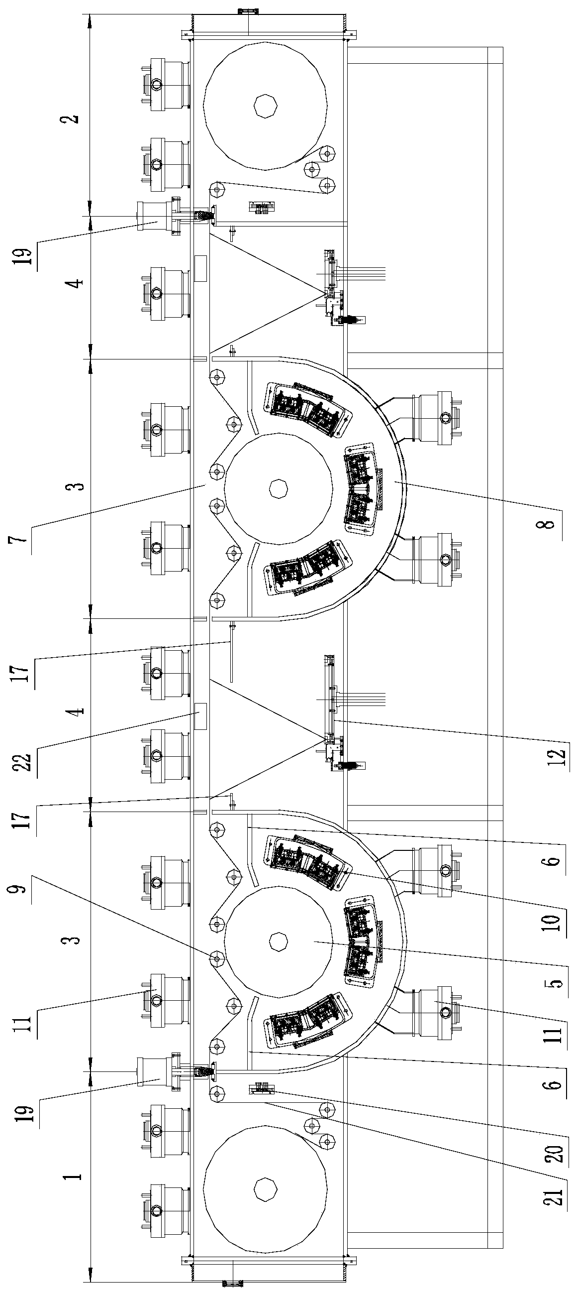
[0034] In this embodiment, a roll-to-roll optical coating device based on magnetron sputtering and electron gun evaporation, such as figure 1 As shown, it includes a plurality of vacuum chambers connected in a straight line. The two vacuum chambers at both ends are unwinding chamber 1 and winding chamber 2 respectively. Two magnetron sputtering chambers are alternately arranged between the unwinding chamber and the winding chamber. Coating chamber 3 and two electron guns evaporate coating chamber 4 . In the structure of the device, the number of magnetron sputtering coating chambers and electron gun evaporation coating chambers can be selected and installed according to the actual needs of different types of substrates. After each substrate passes through a magnetron sputtering coating chamber or an electron gun evaporation coating chamber A film layer can be formed, and the final film thickness is related to the number of magnetron sputtering coating chambers and electron gun...

Embodiment 2

[0041] In this embodiment, a winding-type optical coating method based on magnetron sputtering and electron gun evaporation, the silicon oxide optical film coating is realized through the winding-type optical coating device described in Embodiment 1, and the process is as follows:

[0042] (1) release the substrate 21 in the unwinding chamber;

[0043] (2) The substrate enters the magnetron sputtering coating chamber for magnetron sputtering coating treatment, forming a primary silicon oxide film layer on the surface of the substrate;

[0044] (3) The substrate enters the electron gun evaporation coating chamber for electron gun evaporation coating treatment to form a secondary silicon oxide film layer;

[0045] (4) Repeat steps (2) to (3) until the number of film layers meets the process requirements, and the coated substrate enters the winding chamber for winding.

[0046] In the above method, in the electron gun evaporation coating chamber, the base material is subjected t...

Embodiment 3

[0049] In this embodiment, a winding-type optical coating method based on magnetron sputtering and electron gun evaporation, the winding-type optical coating device described in Embodiment 1 is used to achieve silicon oxide / titanium oxide optical film coating, and the process is as follows:

[0050] (1) release the base material 21 in the roll chamber;

[0051] (2) The substrate enters the magnetron sputtering coating chamber for magnetron sputtering coating treatment, forming a primary silicon oxide film layer on the surface of the substrate;

[0052] (3) The substrate enters the electron gun evaporation coating chamber for electron gun evaporation coating treatment to form a secondary silicon oxide film layer;

[0053] (4) The base material enters the next magnetron sputtering coating chamber for magnetron sputtering coating treatment, while removing the silicon oxide with weak adhesion on the surface of the secondary silicon oxide film layer, a primary titanium oxide film l...


PUM


Abstract

The invention discloses a winding type optical coating device and method based on magnetron sputtering and electron gun evaporation. The device comprises a plurality of vacuum chambers which are linearly connected, wherein two vacuum chambers positioned at two ends are an unwinding chamber and a winding chamber respectively; at least one magnetron sputtering coating chamber and at least one electron gun evaporation coating chamber are arranged between the unwinding chamber and the winding chamber; and when a plurality of magnetron sputtering coating chambers and/or electron gun evaporation coating chambers are arranged, the magnetron sputtering coating chambers and the electron gun evaporation coating chambers are alternately arranged. The method comprises the following steps of alternately performing magnetron sputtering coating treatment and electron gun evaporation coating treatment on a base material, and coating a silicon oxide optical film or a silicon oxide/titanium oxide optical film. According to the winding type optical coating device and method disclosed by the invention, the magnetron sputtering coating and electron gun evaporation coating are combined, so that high binding force is formed between the film and a workpiece or the base material while the structural compactness of the film can be guaranteed, the coating effect of the workpiece or the base material is effectively improved, and the optical performance of the coated product is improved.

Description

technical field [0001] The invention relates to the technical field of vacuum coating, in particular to a winding optical coating device and method based on magnetron sputtering and electron gun evaporation. Background technique [0002] In the field of vacuum coating, silicon oxide optical film and silicon oxide / titanium oxide optical film are generally processed by magnetron sputtering coating, but in the existing processing technology and processing equipment, this processing method often has the following obvious defects: [0003] (1) The structure of the film layer formed by magnetron sputtering coating process is generally relatively dense, and the bonding force with the substrate is weak, so it is difficult to form a good film layer, which affects the optical properties of the coated product; [0004] (2) The film forming speed of magnetron sputtering coating is relatively slow, so it is difficult to form a thicker film layer on the surface of the substrate, and the c...

Claims


Application Information

Patent Timeline
Patent Type & Authority Applications(China)
IPC IPC(8): C23C14/56C23C14/35C23C14/30C23C14/08C23C14/10C23C14/54
CPCC23C14/083C23C14/10C23C14/246C23C14/30C23C14/35C23C14/54C23C14/562
Inventor 朱建明
Owner ZHAOQING KERUN VACUUM EQUIP
Why Eureka
Try Eureka