Apparatus and method for processing, coating or curing a substrate

A technology for coating substrates and equipment, applied in the direction of pretreatment of surfaces, devices for applying liquid to surfaces, coatings, etc., which can solve the problems of uneven power supply of runways, high engineering tolerances, and long-term feasibility affecting uniformity. Achieve the effect of reducing plasma quenching, reducing engineering tolerances, and reducing impact

Pending Publication Date: 2020-07-14
CAMVAC
View PDF15 Cites 0 Cited by
  • Summary
  • Abstract
  • Description
  • Claims
  • Application Information

AI Technical Summary

Problems solved by technology

However, this arrangement has many disadvantages
Specifically, it is very difficult to ensure that the runway is stable and the energy supply is balanced
Any differences and variations in air pressure in the vicinity of runways can lead to uneven supply of power to individual runways, resulting in local variations in applied power, affecting the uniformity of the material produced and the eventual long-term viability of any such process
Therefore, when multiple independent raceways are generated from a single power source, this arrangement requires very high engineering tolerances and tight control, as well as consistency of magnet and process pressure

Method used


Image

  • Apparatus and method for processing, coating or curing a substrate
  • Apparatus and method for processing, coating or curing a substrate
  • Apparatus and method for processing, coating or curing a substrate

Examples


Embodiment Construction

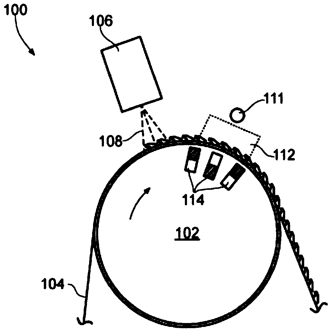
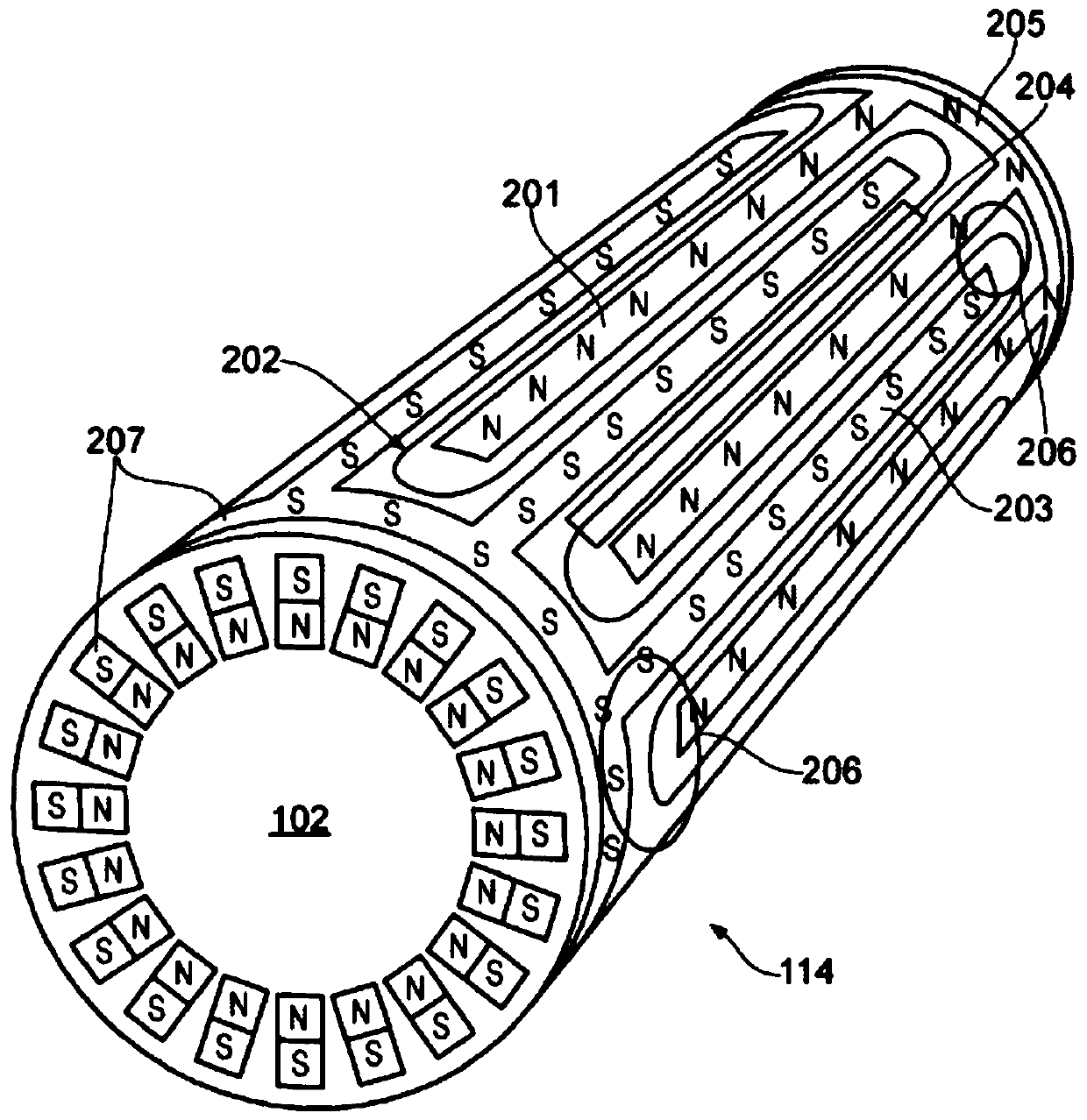
[0053] figure 1 Apparatus 100 for treating, coating or curing a substrate is shown. The apparatus 100 includes a rotating drum 102 for conveying a moving web (web) substrate 104 over the surface of the drum 102 . Adjacent the drum 102 is provided a precursor inlet 106 arranged to apply a precursor 108 to the substrate 104 as the substrate 104 passes under the precursor inlet 106 . Inside the drum 102 there is an array of magnets 114 . The plasma region 112 can be generated by charging the drum relative to the counter electrode 111 using a suitable power source (not shown). Magnet array 114 is fixed such that when drum 102 rotates, magnet array 114 does not rotate with drum 102 but allows the circumferential surface of drum 102 and the film substrate 104 being conveyed to pass thereover. The counter electrode 111 may be of any shape, and may carry an electric charge opposite to the drum, or be grounded. Additionally, electrode 111 may be part of the vacuum chamber or device...


PUM


Abstract

An apparatus for processing or curing a substrate, the apparatus comprising: a support (102) arranged to transport a moving flexible substrate (104), a plasma generator (110) arranged to generate plasma (112), a magnet array (114) arranged to spatially define the plasma, wherein the magnet array comprises: a first elongate magnet (404) having a first polarity; a second elongate magnet (406), substantially parallel to the first elongate magnet, having a second polarity, opposite to the first polarity, such that the first and second elongate magnets define a first straight magnetic flux portion(204); a third elongate magnet (408), substantially parallel to the first elongate magnet,having the first polarity, such that the second and third elongate magnets define a second straight magnetic flux portion, connected to the first straight magnetic flux portion by a first curved magnetic flux portion (206); a fourth elongate magnet (410), substantially parallel to the first elongate magnet, having the second polarity, such that the third and fourth elongate magnets define a third straight magnetic flux portion, connected to the second straight magnetic flux portion by a second curved magnetic flux portion.

Description

Background technique [0001] Transparent ceramic-based barrier coatings are suitable for a variety of applications, including packaging oxygen- or moisture-sensitive food products, encapsulating gas- or moisture-sensitive electronic product components, and various other functional applications requiring barrier properties. These coatings can be applied to flexible substrates using a roll to roll process. [0002] Various methods of producing barrier coatings are known, for example, high-speed physical vapor deposition (Physical Vapour Deposition, PVD). This method is relatively high-speed and low-cost, but produces poor barriers. Enhanced barrier properties can be achieved by a variety of known techniques, including reactive sputtering, chemical vapor deposition, and atomic layer deposition. However, all of these techniques are slow and therefore expensive, especially when used in roll-to-roll processing. [0003] Plasma Enhanced Chemical Vapor Deposition (PECVD) is also a k...

Claims


Application Information

Patent Timeline
Patent Type & Authority Applications(China)
IPC IPC(8): H01J37/32C23C14/35C23C16/50H01J37/34
CPCC23C14/35C23C16/50H01J37/32669H01J37/32761H01J37/3405H01J37/345H01J37/3452C23C14/351C23C16/545B05D3/147B05D3/207B05D2252/02C23C14/562C23C16/45536H01J37/3408
Inventor 亚历山大·约翰·托平詹姆斯·蒂乌·希普曼罗伯特·威廉·贾曼
Owner CAMVAC
Why Eureka
Try Eureka