Induced draft fan inlet flue gas flow measuring device and method

A technology of flue gas flow and measurement device, which is applied to the volume/mass flow generated by mechanical effects, the detection of fluid flow by measuring differential pressure, the electrochemical variables of materials, etc. Simple method, short time-consuming effect

Pending Publication Date: 2020-08-11
CHINA DATANG CORP SCI & TECH RES INST CO LTD EAST CHINA BRANCH +1
View PDF1 Cites 2 Cited by
  • Summary
  • Abstract
  • Description
  • Claims
  • Application Information

AI Technical Summary

Problems solved by technology

[0004] The technical problem to be solved by the present invention lies in the problems of the prior art flue gas flow measuremen

Method used


Image

  • Induced draft fan inlet flue gas flow measuring device and method
  • Induced draft fan inlet flue gas flow measuring device and method
  • Induced draft fan inlet flue gas flow measuring device and method

Examples


Embodiment 1

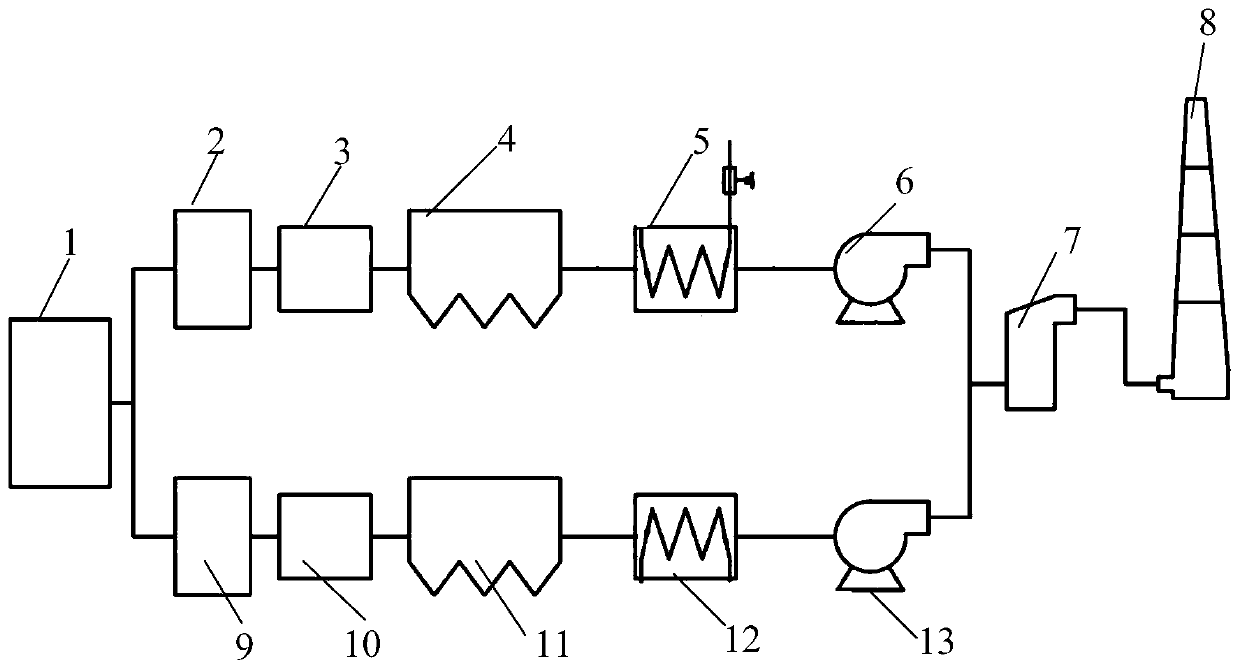
[0051] Such as figure 1 As shown, a flue gas flow measurement device at the inlet of an induced draft fan, including a boiler 1, a first SCR de-pinning device 2, a first air preheater 3, a first dust collector 4, and a first low-temperature economizer connected in sequence through pipelines 5. The first induced draft fan 6, the desulfurization tower 7 and the chimney 8, also includes the second SCR destocking device 9, the second air preheater 10, the second dust collector 11, the second low temperature economizer 12 and the second induced draft fan 13 , the boiler 1, the second SCR depinning device 9, the second air preheater 10, the second dust collector 11, the second low temperature economizer 12, the second induced draft fan 13 and the desulfurization tower 7 are connected in sequence through pipelines.

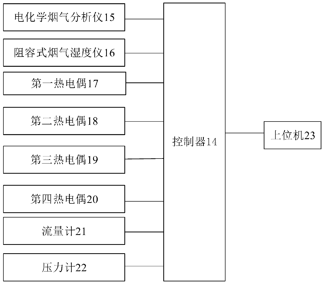
[0052] Such as figure 2 As shown, the pipeline in front of the first low-temperature economizer 5 is provided with an electrochemical flue gas analyzer 15 electrically...

Embodiment 2

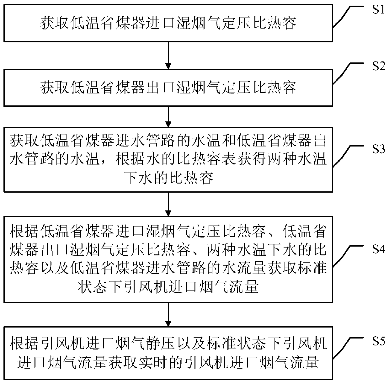
[0057] Such as image 3 As shown, corresponding to Embodiment 1 of the present invention, Embodiment 2 of the present invention also provides a method for measuring flue gas flow at the inlet of an induced draft fan, which is applied to a coal-fired power unit equipped with a low-temperature economizer. The method includes:

[0058] Step S1: Obtain the specific heat capacity of wet flue gas at constant pressure at the inlet of the low-temperature economizer; the specific process is:

[0059] Collect the volume fraction φ of oxygen in the dry flue gas imported from the low-temperature economizer O2 , the volume fraction of carbon dioxide in dry flue gas φ CO2 , the volume fraction of water vapor in wet flue gas φ H2O and inlet flue gas temperature T fg.en ;

[0060] Neglecting the influence of trace amounts of carbon monoxide, nitrogen oxides and sulfur dioxide in the flue gas, the formula φ N2 =100-φ O2 -φ CO2 Obtain the volume fraction of nitrogen in the dry flue gas, ...


PUM


Abstract

The invention discloses an induced draft fan inlet flue gas flow measuring device and method. The device comprises a boiler, a first SCR denitration device, a first air preheater, a first dust remover, a first low-temperature economizer, a first induced draft fan, a desulfurizing tower and a chimney which are sequentially connected through a pipeline. An electrochemical flue gas analyzer, a resistance-capacitance type flue gas hygrometer, a first thermocouple and a second thermocouple which are electrically connected with the controller are arranged on a pipeline in front of the first low-temperature economizer. A third thermocouple, a fourth thermocouple, a flow meter and a pressure meter which are electrically connected with the controller are arranged on a pipeline behind the first low-temperature economizer. The device has the advantages that the flue gas flow at the inlet of the induced draft fan is measured, the flue gas flow does not need to be indirectly obtained from slag, slag component extraction does not need to be quantitatively analyzed, the measurement method is simple, and consumed time is short.

Description

technical field [0001] The invention relates to the technical field of flow measurement at the inlet of an induced draft fan for a coal-fired unit equipped with a low-temperature economizer, and more particularly relates to a device and method for measuring the flow of flue gas at the inlet of an induced fan. Background technique [0002] At present, the equipment layout of large coal-fired generating units is compact, the length of the tail pipe of the boiler is short, and there are many elbows. The unevenness of the position velocity field and the large disturbance of the flow field lead to a large error in the measured flue gas flow at the inlet of the induced draft fan. However, the index of flue gas volume at the inlet of the induced draft fan is very important in measuring the performance of the induced draft fan, calculating environmental protection indicators and controlling boiler operation. Therefore, it is of great significance to research and develop a more accu...

Claims


Application Information

Patent Timeline
IPC IPC(8): G01F1/34G01F1/68G01N27/26G01N27/02G01N27/22G01N25/20
CPCG01F1/34G01F1/68G01N25/20G01N27/02G01N27/22G01N27/26
Inventor 吴万范许文良邓中乙潘存华马启磊
Owner CHINA DATANG CORP SCI & TECH RES INST CO LTD EAST CHINA BRANCH
Why Eureka
Try Eureka