
A composite multi-bed visible light mercury removal device and method

A visible light and mercury removal technology, applied in separation methods, chemical instruments and methods, gas treatment, etc., can solve the problems of increasing dust collector load and high price, and achieve good benefits, reduce mercury concentration, and high efficiency.

Active Publication Date: 2022-07-05
HENAN POLYTECHNIC UNIV
View PDF0 Cites 0 Cited by
  • Summary
  • Abstract
  • Description
  • Claims
  • Application Information

AI Technical Summary

Problems solved by technology

However, as an effective adsorbent, powdered activated carbon has the advantage of high efficiency and the disadvantage of relatively high price.
And increase the load of the dust collector

Method used


Image

  • A composite multi-bed visible light mercury removal device and method
  • A composite multi-bed visible light mercury removal device and method
  • A composite multi-bed visible light mercury removal device and method

Examples


Embodiment 1

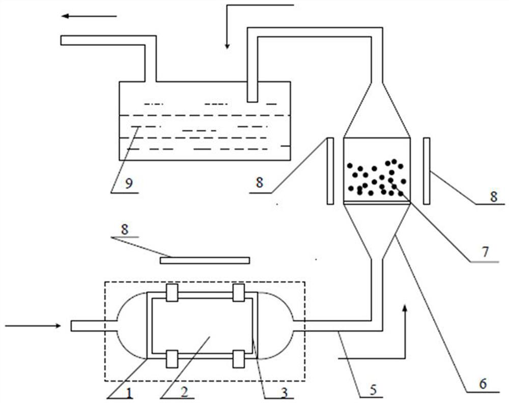
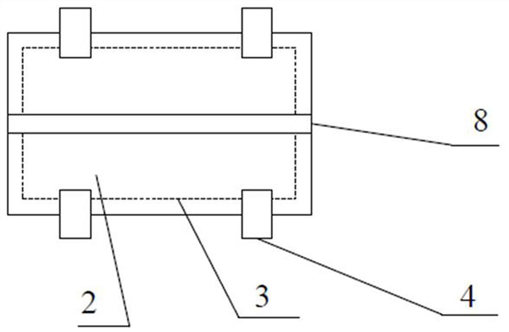
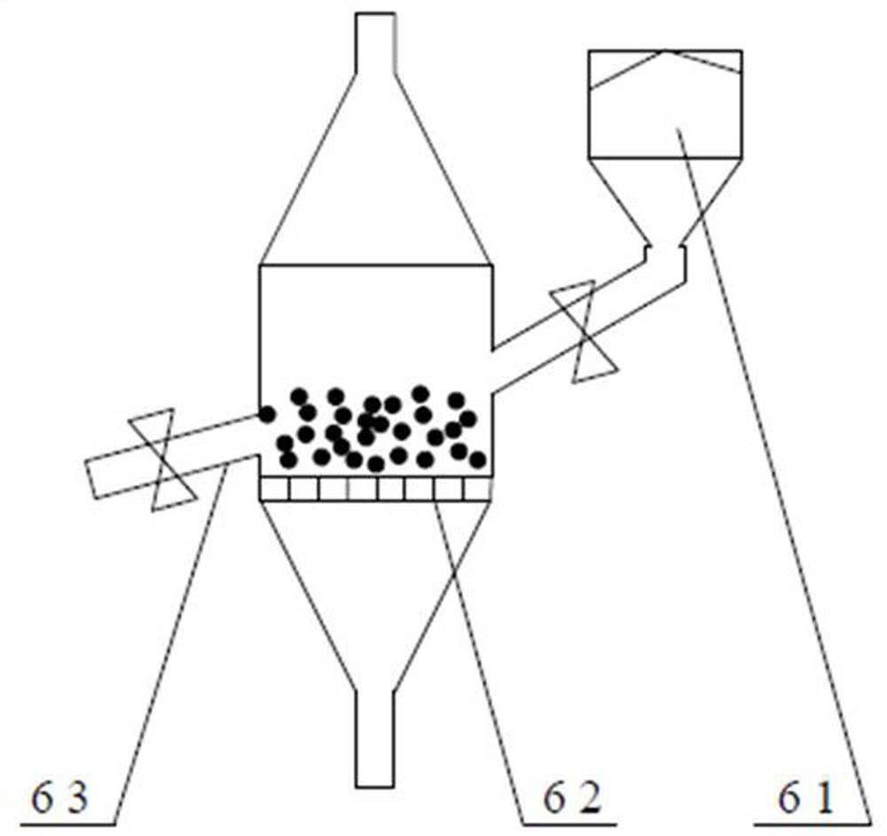
[0030] like figure 1 As shown, a compound multi-bed visible light mercury removal device includes a plexiglass fixed bed 1, a bubbling bed 6, and a mercury recovery pool 9, wherein, as shown in the figure figure 2 As shown, a catalyst carrier 2 is placed in the plexiglass fixed bed 1, and the catalyst carrier 2 is sealed in the plexiglass fixed bed 1 with quartz glass 3 through a sealing clip 4, and the catalyst carrier 2 is covered with an appropriate amount of catalyst, such as Ag- AgI-Bi 5 O 7 Br; the plexiglass fixed bed 1 is connected to the bubbling bed 6 through the pipeline 5, and the bubbling bed 6 includes a silo 61, a cloth sealing plate 62, and a discharge port 63, such as image 3 As shown, there are catalyst particles 7 in the bubbling bed 6; In this embodiment, fluorescent lamps 8 are arranged around the plexiglass fixed bed 1 and the bubbling bed 6 . In this embodiment, a fan is provided on the pipeline 5 for entering the flue gas into the mercury removing...

Embodiment 2

[0033] The method that adopts the composite multi-bed visible light mercury removal device of embodiment 1 to remove mercury in flue gas comprises the following steps:

[0034] Step (1), cover the catalyst carrier 2 with an appropriate amount of catalyst Ag-AgI-Bi 5 O 7 Br, put it into the plexiglass fixed bed 1, then cover the quartz glass 3, fix it with four sealing clips 4 and press it tightly without air leakage, turn on the fluorescent lamp 8, and radiate the catalyst carrier;

[0035] Step (2), enter the catalyst particles 7 into the bubbling bed 6 through the silo 61, and turn on the fluorescent lamp 8 to radiate it;

[0036] In step (3), the flue gas enters the plexiglass fixed bed 1 and reacts with the catalyst put into it after being pressurized by the booster fan through the pipeline 5, and the reacted gas enters the bubbling bed 6 and the catalyst particles 7 through the pipeline 5. Continue the reaction, the gas that reacts completely enters the mercury recovery...


PUM


Abstract

The invention discloses a composite multi-bed visible light mercury removal device and method, and relates to the technical field of flue gas removal from coal-fired, biomass-fired power plants and steel mills. The mercury removal device includes a plexiglass fixed bed, a bubbling bed, and a mercury recovery pool, wherein a catalyst carrier is placed in the plexiglass fixed bed, and an appropriate amount of catalyst is covered on the catalyst carrier; the plexiglass fixed bed passes through pipes and drums. The bubbling bed is connected, and there are catalyst particles in the bubbling bed; the bubbling bed is connected with the mercury recovery tank through a pipeline, and fluorescent lamps are arranged around the plexiglass fixed bed and the bubbling bed. Using the mercury removal device, SO can be removed through the deacidification tower 2 , NO x The flue gas from the flue gas and soot is introduced into the mercury removal device. After the oxidation reaction of the catalyst, the purpose of oxidizing zero-valent mercury into divalent mercury is achieved, and then absorbed by chemical absorption method to achieve the purpose of removing mercury in the flue gas. The invention not only solves the air pollution problem of zero-valent mercury and divalent mercury in the flue gas, but also recovers the mercury resources in the flue gas, and has good benefits.

Description

technical field [0001] The invention relates to a mercury removal (Hg) device for flue gas of coal-fired, biomass-fired power plants and steel mills to achieve the purpose of removing mercury from the flue gas. In particular, it refers to a catalyst (chemical formula: Ag-AgI-Bi) added to the mercury removal device. 5 O 7 Br) method, through the oxidation of zero-valent mercury, and then through chemical absorption to achieve the purpose of removing mercury in flue gas. Background technique [0002] Mercury is an element, so it cannot be destroyed or created. Mercury is one of the most toxic heavy metals in the environment, and the toxicity of various mercury compounds varies widely. Mercury chloride in inorganic mercury is a highly toxic substance; phenylmercury in organic mercury decomposes quickly and is not toxic, while methylmercury is easily absorbed into the human body, not easily degraded, and excreted very slowly, especially in the brain. Accumulation, the most t...

Claims


Application Information

Patent Timeline
Patent Type & Authority Patents(China)
IPC IPC(8): B01D53/75B01D53/86B01D53/78B01D53/64
CPCB01D53/75B01D53/869B01D53/8665B01D53/78B01D53/64B01D2257/602B01D2258/0283
Inventor 陈国艳郑宏祥张安超邓浩鑫陈小砖李海霞孙志君孟凡茂温小萍王发辉盛伟
Owner HENAN POLYTECHNIC UNIV
Learn More