Ultrasonic detection device and medical imaging system

An ultrasonic detection and ultrasonic transducer technology, applied in medical science, ultrasonic/sonic/infrasonic Permian technology, ultrasonic/sonic/infrasonic image/data processing, etc. Infection and other problems, to achieve the effect of uniform thickness, saving time and avoiding deformation

Pending Publication Date: 2020-08-18
武汉和视光声科技有限公司
View PDF0 Cites 4 Cited by
  • Summary
  • Abstract
  • Description
  • Claims
  • Application Information

AI Technical Summary

Problems solved by technology

[0004] Aiming at at least one defect or improvement requirement of the prior art, the present invention provides an ultrasonic detection device and a medical imaging system, in which a flexible film is laid on the surface of the opening of a container containing an ultrasonic transducer, and on both sides of the flexible film Create a pressure differential to uniformly stretch the flexible film to deform it, creating a concave cavity that can accommodate the part of the human body to be examined, so that the part to be tested can be penetrated enough into the container filled with ultrasonic couplant to allow the ultrasonic transducer to receive The photoacoustic or ultrasonic signal of the inspected part; the flexible film not only effectively isolates the ultrasonic coupling agent in the container and the inspected part, but most importantly, the thickness of the flexible film gradually becomes thinner during the stretching process, and the flexible film is subjected to The pressure difference is uniform in all directions, so the thickness of the stretched flexible film is uniform, and the imaging effect will not be affected by the uneven attenuation of the signal; the purpose is to solve the existing ultrasonic detection device that is easy to cause different Problems with cross-infection between subjects and contamination of ultrasound transducers

Method used


Image

  • Ultrasonic detection device and medical imaging system
  • Ultrasonic detection device and medical imaging system
  • Ultrasonic detection device and medical imaging system

Examples


Embodiment 1

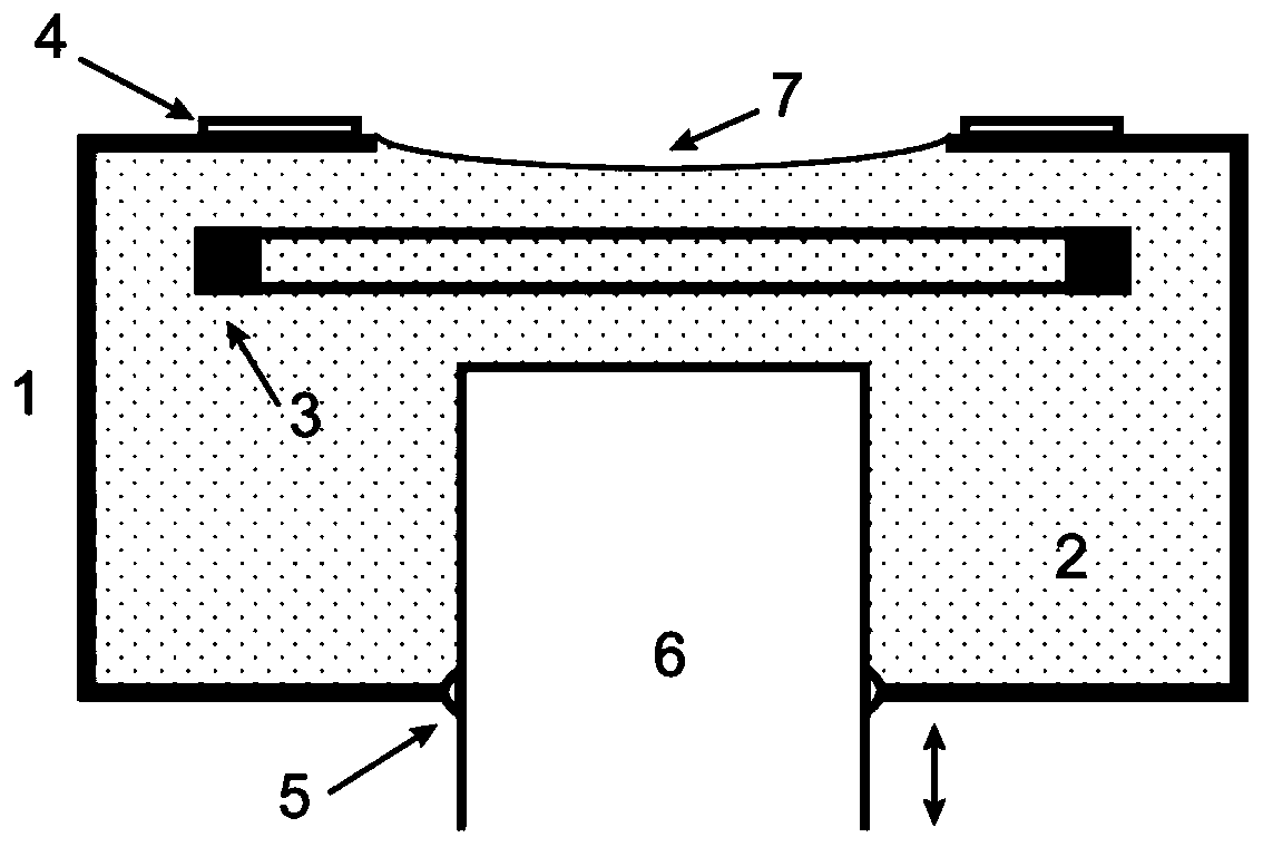
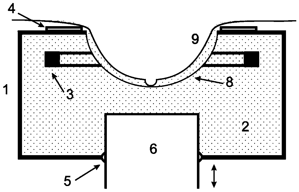
[0034] figure 1 It is a schematic structural diagram of the ultrasonic detection device provided in Embodiment 1, such asfigure 1 As shown, the ultrasonic detection device includes a container 1 filled with an ultrasonic coupling agent 2, and an ultrasonic transducer array 3 is fixedly installed inside the container 1. In this embodiment, a plurality of ultrasonic transducers are preferably arranged in a ring to form an ultrasonic transducer. Transducer array 3, the ultrasonic transducer array 3 can move up and down, and every time it moves to each position, it collects the ultrasonic signal of the cross section of the inspected part at that position, so as to realize the two-dimensional imaging of a cross section. The position of the transducer array 3 is used to realize three-dimensional imaging of the inspected part.

[0035] The main function of the ultrasonic coupling agent 2 is to conduct ultrasonic signals. In this embodiment, water is used as the coupling agent; the to...

Embodiment 2

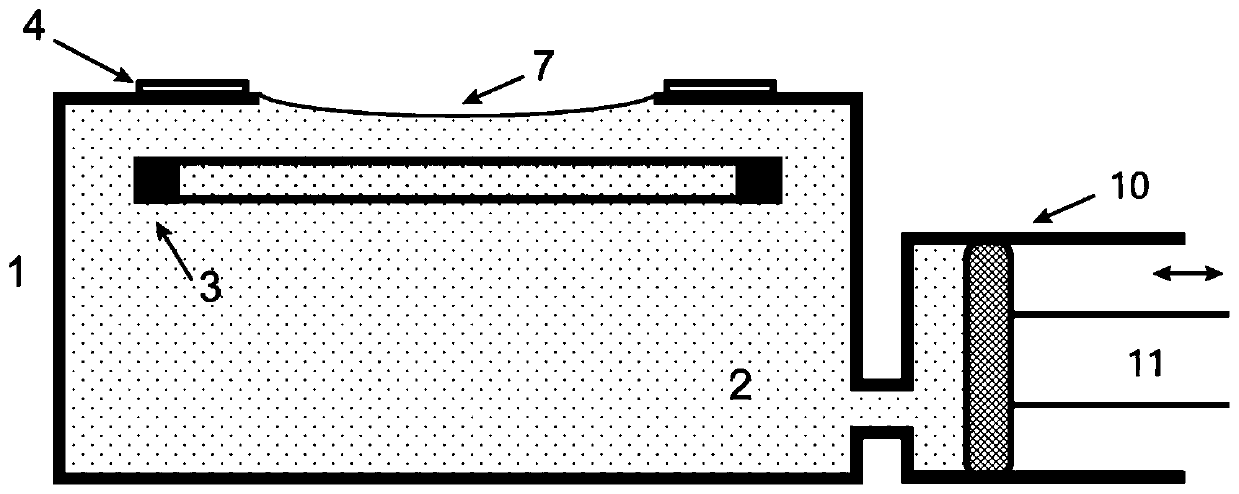
[0039] image 3 It is a schematic diagram of the structure of the ultrasonic detection device provided in the second embodiment. The difference between the structure of the ultrasonic detection device and the first embodiment is that a structural member similar to a syringe is used to replace the cylinder 6 in the first embodiment, such as image 3 As shown, the syringe-like structure includes a cavity 10 communicating with the container 1, and a pull rod 11 arranged inside the cavity 10 and forming a sealing fit with the inner wall of the cavity 10; the pull rod 11 can be inside the cavity 10 to move;

[0040] After the polymer film 7 is fixed, the container 1 forms a closed environment. When the pull rod 11 moves under the action of an external force, the water inside the container 1 is pumped out into the cavity 10, so that the water pressure inside the container 1 Reduce, because watertightness causes the air pressure above polymer film 7 to apply force to polymer film 7,...

Embodiment 3

[0048] This embodiment provides a medical imaging system, including an optical excitation device, an image reconstruction device, and the ultrasonic detection device in Embodiment 1 or Embodiment 2, where the ultrasonic detection device is electrically connected to the image reconstruction device;

[0049] Among them, the optical excitation device is mainly used to emit ultrasonic or photoacoustic signals and irradiate them on the tested parts; the ultrasonic or photoacoustic signals are absorbed by the tested parts and converted into transient heat energy, and then ultrasonic waves are emitted due to thermoelastic expansion;

[0050] The ultrasonic detection device collects the ultrasonic signal of the inspected part, converts the ultrasonic signal into an electrical signal and sends it to the image reconstruction device, and the image reconstruction device reconstructs the corresponding ultrasonic signal into a photoacoustic image according to the electrical signal, and obtain...


PUM

PropertyMeasurementUnit
Thicknessaaaaaaaaaa

Abstract

The invention discloses an ultrasonic detection device and a medical imaging system. The ultrasonic detection device comprises an ultrasonic transducer and a container for accommodating the ultrasonictransducer, the interior of the container is filled with an ultrasonic coupling agent, and the working surface of the container is provided with an opening; a transparent flexible film is laid on thesurface of the opening, the flexible film responds to the pressure difference between the two sides of the flexible film and is evenly stretched in the direction close to the ultrasonic transducer, aconcave cavity capable of containing a detected part of a human body is generated, and the depth of the concave cavity can be adjusted so as to be matched with detected parts of different sizes. According to the invention, the flexible film is uniformly stretched by adopting pressure control, the thickness of the flexible film is gradually reduced in the stretching process, the thickness of the stretched flexible film is uniform, and the imaging effect is not influenced by non-negligible attenuation on illumination or sound signals; the flexible film effectively isolates the ultrasonic coupling agent and the examined part in the container, the ultrasonic coupling agent does not need to be replaced for different patients, and cross infection between different examinees cannot be caused.

Description

technical field [0001] The invention belongs to the technical field of ultrasonic imaging, and more particularly relates to an ultrasonic detection device and a medical imaging system, which are suitable for photoacoustic tomography and ultrasonic tomography of raised parts of a human body. Background technique [0002] Ultrasonic imaging methods (including ultrasonic imaging and photoacoustic imaging, etc.) have become an important means of medical diagnosis, and ultrasonic detection depends on receiving ultrasonic signals with ultrasonic transducers. When ultrasonic waves are incident on the interface between two different media, the greater the difference in acoustic impedance between the two, the greater the reflection coefficient, and the less energy the ultrasonic waves will pass through the interface into another medium. If there is an air gap between the ultrasonic transducer and the tested part, or direct "dry contact", the air layer between the ultrasonic probe and...

Claims


Application Information

Patent Timeline
IPC IPC(8): A61B5/00A61B8/08A61B8/00
CPCA61B5/0095A61B5/4312A61B8/0825A61B8/085A61B8/406A61B8/4488A61B8/4494A61B8/5261
Inventor 施钧辉季格兰胡群易山刘民伍冲蔡明斌刘凯
Owner 武汉和视光声科技有限公司
Why Eureka
Try Eureka