High-speed shearing emulsification device and flotation complete equipment

An emulsification device and high-speed shearing technology, which is applied in flotation, spraying devices, spraying devices with movable outlets, etc., can solve the problems of complex structure, inability to add uniformly, and inability to provide power pulp flotation agents, etc., to achieve the device structure Simple, good emulsifying effect

Active Publication Date: 2020-08-25
ANHUI UNIV OF SCI & TECH
View PDF7 Cites 2 Cited by
  • Summary
  • Abstract
  • Description
  • Claims
  • Application Information

AI Technical Summary

Problems solved by technology

[0003] However, for the current flotation device and auxiliary pretreatment device, they are usually separated in practical application, occupy a large area and the transportation of ore slurry is usually pumped, so that after each stage of pumping, the flotation device There is a huge energy loss in the auxiliary device and the auxiliary device. For example, after the pulp is sent to the pretreatment device, the energy carried by the pulp is attenuated to zero, and the pulp pretreatment equipment, chemical addition equipment, etc. are running themselves and pumping materials to the flotation machine. All consume a lot of energy and the equipment will occupy a lot of plant area, and the cost of equipment and infrastructure is high
[0004] For improving the flotation efficiency, the addition method of the agent will greatly affect the bubble mineralization system, and then affect the flotation efficiency. Currently, the commonly used flotation agents are mainly foaming agents and collectors. For foaming agents , mainly to change the surface tension of the gas-liquid interface. The addition of the existing foaming agent is mainly added during the flotation process of the flotation machine. Due to the inability to add uniformly and effectively act on the gas-liquid interface, resulting in a large amo

Method used


Image

  • High-speed shearing emulsification device and flotation complete equipment
  • High-speed shearing emulsification device and flotation complete equipment
  • High-speed shearing emulsification device and flotation complete equipment

Examples


Embodiment Construction

[0058] The following will clearly and completely describe the technical solutions in the embodiments of the present invention with reference to the accompanying drawings in the embodiments of the present invention. Obviously, the described embodiments are only some, not all, embodiments of the present invention. Based on the embodiments of the present invention, all other embodiments obtained by persons of ordinary skill in the art without making creative efforts belong to the protection scope of the present invention.

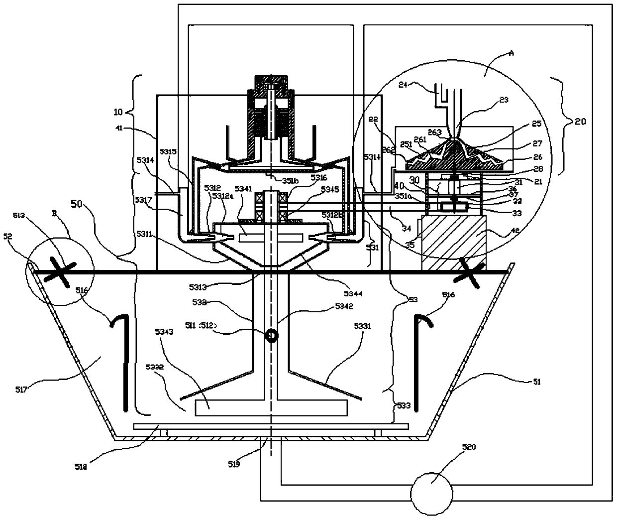
[0059] The embodiment of the present invention discloses a high-speed shear emulsification device comprising:

[0060] Emulsification tank 22, the bottom of the emulsification tank 22 has an emulsifier outlet;

[0061] Medicament sprayer 23, the top of medicament sprayer 23 is installed in emulsification tank 22, and is connected with water flow ejection pipe 24 near the nozzle inlet of medicament sprayer 23, and the nozzle outlet of medicament sprayer 23 is p...


PUM


Abstract

The invention discloses a high-speed shearing emulsification device and flotation complete equipment. The high-speed shearing emulsification device comprises an emulsifying tank, a medicament spray head, a rotary fluted disc and a fixed fluted disc; the medicament spray head is mounted at the top end of the emulsifying tank and is connected with a water flow injection pipe; the rotary fluted discand the fixed fluted disc are oppositely arranged; a sawtooth-shaped shearing flow channel is formed between the rotary fluted disc and the fixed fluted disc; a motor is connected with the bottom endof the rotary fluted disc through a transmission shaft; the rotary fluted disc is driven by the motor to rotate at a high speed; a mixed solution of a collecting agent and water is sheared at a high speed in the sawtooth-shaped shearing flow channel to be fully mixed and emulsified. The flotation complete equipment is simple in structure and good in emulsification effect; the flotation complete equipment integrates an injection atomization device, the high-speed shearing emulsification device and a double-connection-wheel jet agitation mechanism, and therefore, the size of the equipment is greatly reduced, area occupied by the equipment is greatly reduced, the energy consumption of ore pulp pumping is reduced, and meanwhile, mineral separation efficiency is improved.

Description

technical field [0001] The invention relates to the technical field of mineral separation equipment, in particular to a high-speed shear emulsification device and a complete set of flotation equipment. Background technique [0002] In the process of mineral separation, flotation is the first choice for the separation of fine-grained coal. At present, the mainstream flotation devices mainly include mechanical agitation flotation machines, jet flotation machines, flotation columns, etc. Previously, it was usually equipped with auxiliary pretreatment devices such as pulp preprocessor, flotation agent addition equipment, and agent emulsification equipment, and the auxiliary pretreatment device was very important for efficient flotation of ore pulp. [0003] However, for the current flotation device and auxiliary pretreatment device, they are usually separated in practical application, occupy a large area and the transportation of ore slurry is usually pumped, so that after each ...

Claims


Application Information

Patent Timeline
IPC IPC(8): B03D1/16B03D1/14B05B3/10B01F3/08B01F5/02B01F7/26B01F9/18B01F13/10B01F27/93B01F29/86
CPCB03D1/16B03D1/1418B03D1/1443B03D1/1456B03D1/145B03D1/1468B03D1/1475B05B3/1014B01F23/41B01F25/20B01F27/93B01F29/86B01F33/821
Inventor 朱金波王超周伟朱宏政
Owner ANHUI UNIV OF SCI & TECH
Why Eureka
Try Eureka