A fully automatic periodic drum resistance furnace
A fully automatic, resistance furnace technology, used in furnaces, rotary drum furnaces, furnace types, etc., can solve the problems of direct cooling of processed materials, large resistance furnaces, low processing efficiency, etc., to reduce heat loss and reduce equipment volume. , the effect of high production efficiency
- Summary
- Abstract
- Description
- Claims
- Application Information
AI Technical Summary
Problems solved by technology
Method used
Image
Examples
Embodiment 1
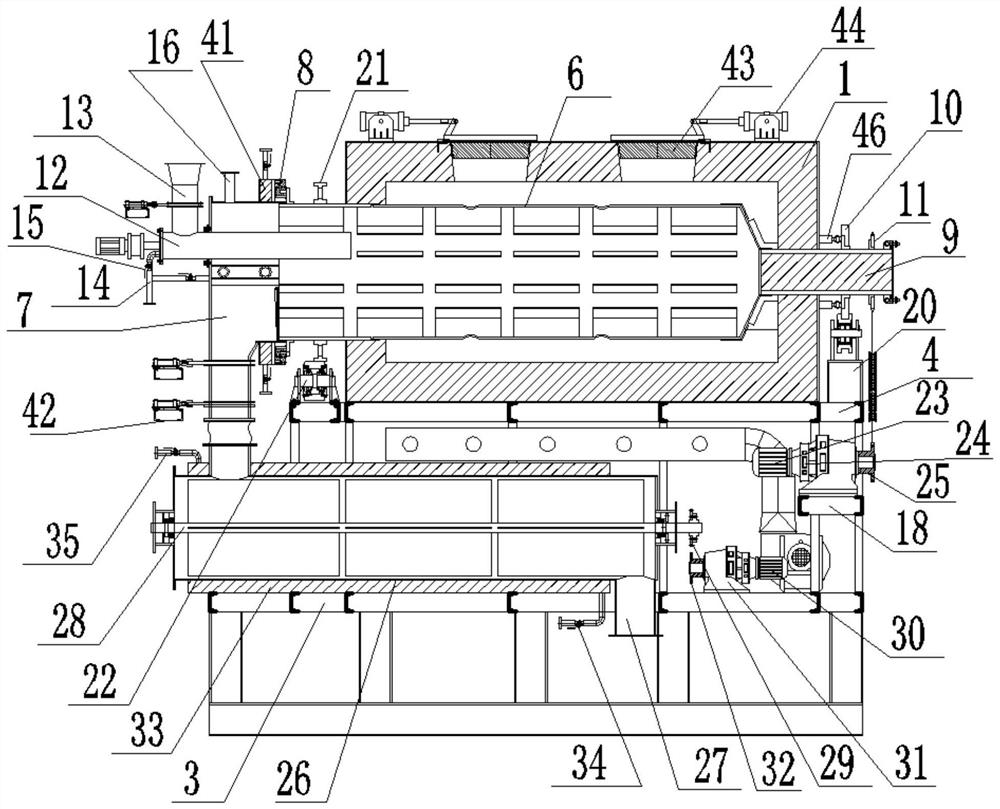
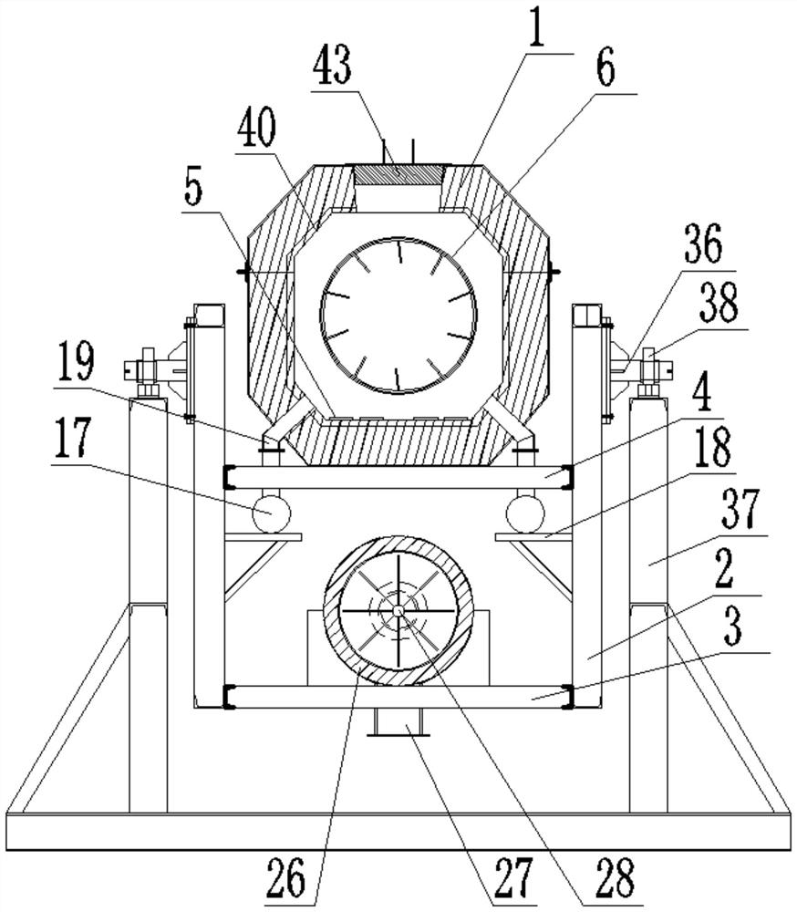
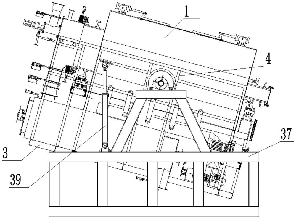
[0038]SeeFigure 1-8 A fully automatic periodic drum resistance furnace according to an embodiment of the present invention includes a furnace body 1, side plates 2 are provided on both sides of the furnace body 1, and a bottom plate 3 is fixed between the lower ends of the side plates 2. A partition 4 is fixed between the middle parts of the side plates 2, the furnace body 1 is fixed on the partition 4, the inner wall of the furnace body 1 is fixed with a heating element 5, and the furnace body 1 is provided with a furnace pot. 6. One end of the furnace pot 6 is provided with a discharge bin 7, and the furnace pot 6 and the discharge bin 7 are connected in rotation through a graphene rotary bearing 8, and the furnace pot 6 is far away from the discharge bin 7 One end of the bin 7 is fixedly provided with a transmission shaft 9 which extends out of the furnace body 1 and the outer wall is fixedly sleeved with a limit plate 10 and a first sprocket 11, and the furnace pot 6 is close to...
Embodiment 2
[0041]SeeFigure 1-2For the furnace body 1, the furnace body 1 is welded by section steel and the inner wall of the furnace body 1 is fixed with an aluminum silicate fiber heat insulation layer 40; for the heating element 5, the heating element 5 is Iron-chromium-aluminum 0Cr25Al5 material resistance tape is wound into a wave shape and fixed on the aluminum silicate fiber heat insulation layer 40 with a ceramic screw; for the graphene rotary bearing 8, a cooling water jacket is installed on one side of the graphene rotary bearing 8 41; For the butterfly valve system, the butterfly valve system includes a number of two pneumatic hard-sealed butterfly valves 42, the pneumatic hard-sealed butterfly valves 42 are installed in the middle of the discharge bin 7.
[0042]Through the above solution of the present invention, the aluminum silicate fiber insulation layer 40 can reduce the heat loss in the furnace body 1, and the iron chromium aluminum 0Cr25Al5 resistance band is fixed on the alumi...
Embodiment 3
[0044]Seefigure 1 with4For the cooling system, the cooling system includes a cooling cover 43 and an electric push rod 44, the number of the cooling cover 43 and the electric push rod 44 is two, and the furnace body 1 is provided with a number of Two heat dissipation holes, each of which is provided with a cooling cover 43, one end of the cooling cover 43 is rotatably mounted on the heat dissipation hole through a hinge, and the cooling cover 43 is fixed on one end close to the hinge A connecting rod 45 is provided and the connecting rod 45 is arranged obliquely. The connecting rods 45 are all hinged with electric push rods 44, and the electric push rods 44 are all hinged to the furnace body 1; for the furnace body 1 , The outer wall of the furnace body 1 close to one end of the limiting disk 10 is installed with a positioning wheel device 46 matching the limiting disk 10.
[0045]Through the above-mentioned solution of the present invention, the cooling cover 43 can be driven by the e...
PUM
 Abstract
Description
Claims
Application Information
 - R&D
- Intellectual Property
- Life Sciences
- Materials
- Tech Scout
- Unparalleled Data Quality
- Higher Quality Content
- 60% Fewer Hallucinations
Browse by: Latest US Patents, China's latest patents, Technical Efficacy Thesaurus, Application Domain, Technology Topic, Popular Technical Reports.
© 2025 PatSnap. All rights reserved.Legal|Privacy policy|Modern Slavery Act Transparency Statement|Sitemap|About US| Contact US: help@patsnap.com


