Al technical title is built by PatSnap Al team. It summarizes the technical point description of the patent document.
A non-leakage, intelligent technology, applied in the direction of pumps, pump devices, pump components, etc., to achieve the effect of improving work efficiency, improving safety, and simple overall structure
Inactive Publication Date: 2020-09-25
HUNAN NEPTUNE PUMP
View PDF9 Cites 4 Cited by
Summary
Abstract
Description
Claims
Application Information
AI Technical Summary
This helps you quickly interpret patents by identifying the three key elements:
Problems solved by technology
Method used
Benefits of technology
Problems solved by technology
[0004] The purpose of the present invention is to provide an intelligent permanent magnet non-leakage pump to solve the problem that there is a large gap between the inner diameter of the long-axis fire pump casing and the outer diameter of the pump lift pipe in the above background technology, and the pump still has the risk of swinging question
Method used
Image
Click on the blue label to locate the original text in one second.
Reading with bidirectional positioning of images and text.
Examples
Embodiment 1
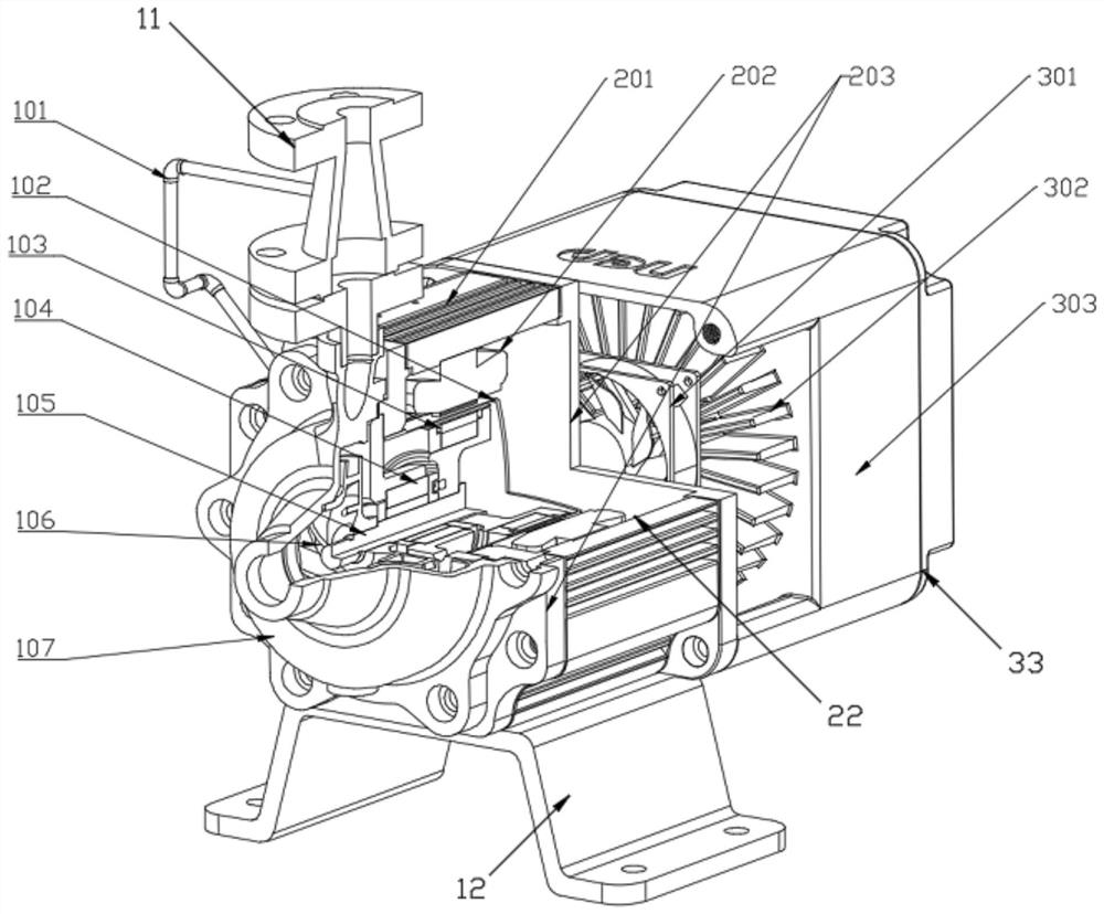
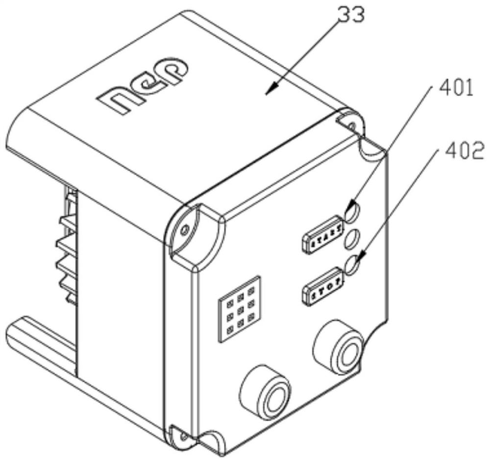
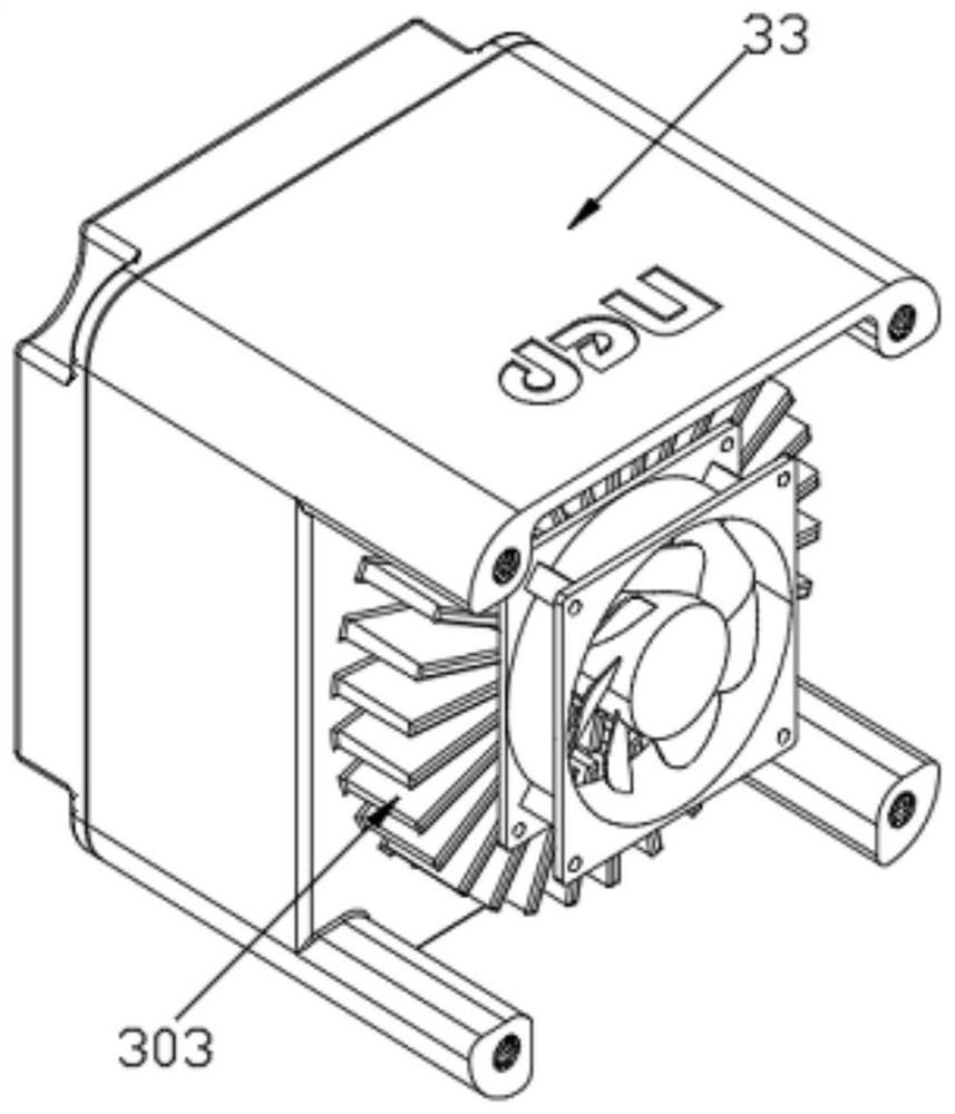
[0031] An intelligent permanent magnet non-leakage pump, such as Figure 1-Figure 3 As shown, it includes a non-leakage pump body 11, a base 12 is installed on the bottom of the non-leakage pump body 11, a permanent magnet synchronous motor stator 22 and an intelligent frequency conversion controller 33 are installed in the non-leakage pump body 11, the non-leakage pump body 11, the permanent The stator 22 of the magnetic synchronous motor and the intelligent frequency conversion controller 33 are connected by a flange assembly 203. The leak-free pump body 11 includes a flow radiator 101, an isolation sleeve 102, a synchronous rotor 103, a bearing 104, a rotating shaft 105, an impeller 106, And the pump housing 107, the permanent magnet synchronous motor stator 22 includes a cooling housing 201 and a stator 202 embedded with three-phase coils, the intelligent frequency conversion controller 33 includes a control box 303, and a cooling fan 301 and some cooling fins are installed...
Embodiment 2
[0041] In the present embodiment, the permanent magnet non-leakage pump of the present invention is compared with the asynchronous frequency conversion magnetic pump, which is as follows:
[0042] 1. Test time: March 25, 2020
[0043] 2. Test location: Hydraulic test workshop of Special Pump Technology Branch of Hunan Naipu Pump Co., Ltd.
[0044] 3. Purpose of the test: Two kinds of motor technical schemes and products are used to drive the same type of non-leakage pump. From the actual test performance data, the current, power, temperature, vibration, noise, etc.
[0046] 5. Description of test motor and pump status:
[0047] (1) Asynchronous motor 1# refers to asynchronous motor + frequency converter + magnetic coupling
[0048] (2) Asynchronous motor 2# refers to asynchronous motor + frequency converter + ...
PUM
Abstract
The invention relates to the technical field of pump equipment, in particular to an intelligent permanent magnet zero-leakage pump. The intelligent permanent magnet zero-leakage pump comprises a zero-leakage pump body, wherein the bottom of the zero-leakage pump body is equipped with a base; a permanent magnet synchronous motor stator and an intelligent variable-frequency controller are mounted inthe zero-leakage pump body; the zero-leakage pump body comprises a flow radiator, an isolating sleeve, a synchronous rotor, a bearing, a rotary shaft, an impeller and a pump shell; the permanent magnet synchronous motor stator comprises a heat dissipation housing and a stator which is embedded with three groups of coils; the intelligent variable-frequency controller comprises a control box; and aheat dissipation fan and a plurality of heat dissipation fins are mounted on the control box. The intelligent permanent magnet zero-leakage pump is simple in integral structure, cancels a magnetic shaft coupler needed for a conventional magnetic pump, adopts an intelligent control module of the intelligent variable-frequency controller to safely monitor a working state of the motor and the pump,upgrades original switch type control to be intelligent protection type control, reduces a connecting link, adopts a permanent magnet synchronous motor to improve work efficiency, improves integral system efficiency, and saves energy consumption of a power grid.
Description
technical field [0001] The invention relates to the technical field of pump equipment, in particular to an intelligent permanent magnet non-leakage pump. Background technique [0002] At present, in the transportation of corrosive media in chemical production, petroleum, electric power, electroplating, dyes, pesticides, papermaking, food, textiles and many other industries, long-term transportation of sulfuric acid, hydrochloric acid and hydrofluoric acid of any concentration under the temperature condition of -20℃~150℃ Non-leakage pumps are required for acid, nitric acid, aqua regia, strong alkali, strong oxidizing agent, organic solvent, reducing agent and other strong corrosive media. When selecting the pump type, the requirements for the pump must meet the requirements for the characteristics of the medium, and reliable shaft seals are required for pumps that transport flammable, explosive, volatile low-temperature media (liquefied petroleum gas, etc.), toxic or expensiv...
Claims
Application Information
Patent Timeline
Application Date:The date an application was filed.
Publication Date:The date a patent or application was officially published.
First Publication Date:The earliest publication date of a patent with the same application number.
Issue Date:Publication date of the patent grant document.
PCT Entry Date:The Entry date of PCT National Phase.
Estimated Expiry Date:The statutory expiry date of a patent right according to the Patent Law, and it is the longest term of protection that the patent right can achieve without the termination of the patent right due to other reasons(Term extension factor has been taken into account ).
Invalid Date:Actual expiry date is based on effective date or publication date of legal transaction data of invalid patent.