A split composite piston and its forming method
A molding method and composite technology, applied in the direction of piston, machine/engine, mechanical equipment, etc., can solve the problems of weld failure, difficult welding process, and deep weld, so as to reduce the level of mechanical stress and improve the reliability of weld. The effect of strong flexibility and process adaptability
- Summary
- Abstract
- Description
- Claims
- Application Information
AI Technical Summary
Problems solved by technology
Method used
Image
Examples
Embodiment 1
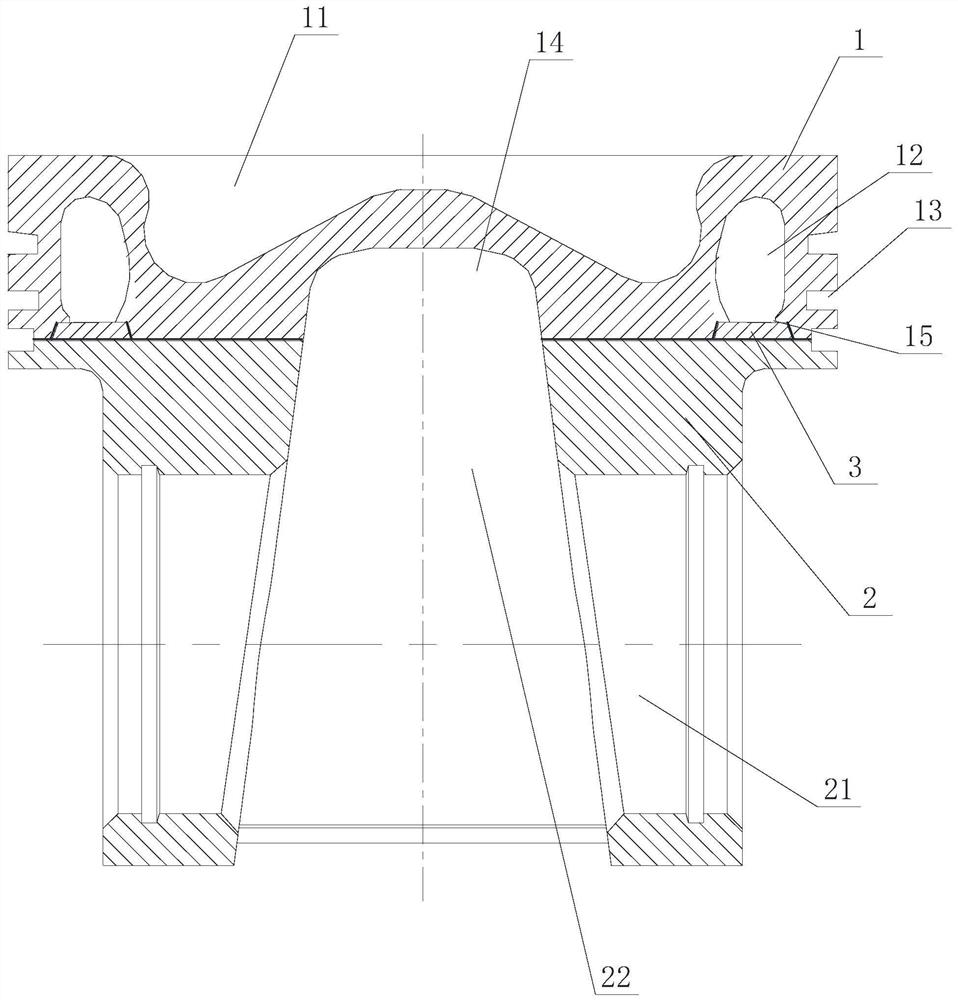
[0075] Figure 1 to Figure 2 Shows the first embodiment of the split composite piston of the present invention, including a split piston head 1 and a piston skirt 2, the piston head 1 is provided with a combustion chamber 11, an annular oil chamber 12, a head ring Groove 13 and head inner cavity 14, piston skirt 2 is provided with pin hole 21 and skirt inner cavity 22, split surface of piston head 1 passes through annular oil chamber 12, split surface of piston head 1 is provided with annular oil chamber 12 The annular compensation port 15 connected at the bottom, the annular compensation port 15 is equipped with an annular compensation plate 3, the bottom surface of the annular compensation plate 3 and the split surfaces on both sides of the annular compensation port 15 of the piston head 1 jointly form a continuous and complete weldable surface , The piston head 1 and the piston skirt 2 are welded and connected along the weldable surface. The present invention reduces the p...
Embodiment 2
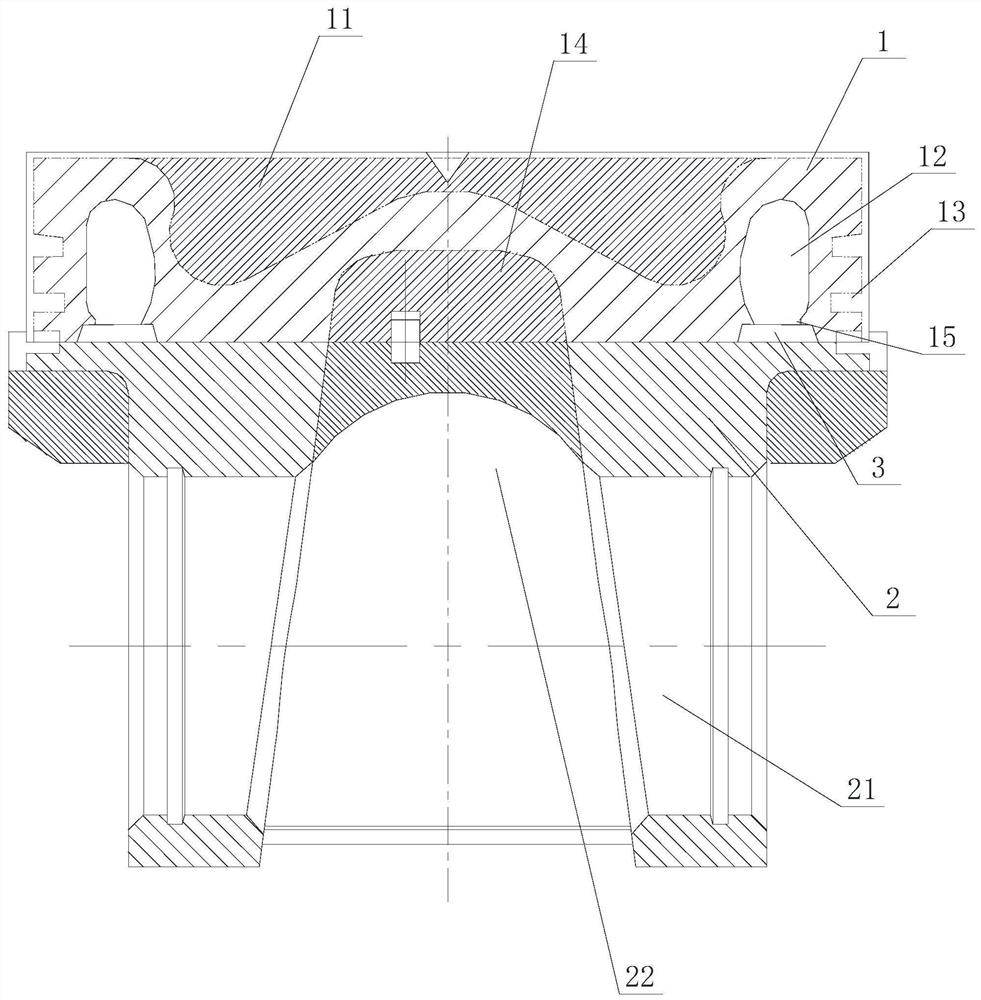
[0077] Figure 4 to Figure 6 Shows the second embodiment of the split composite piston of the present invention, the piston is basically the same as Embodiment 1, the only difference is: in this embodiment, the piston head 1 and the piston skirt 2 are located on the same side of the respective split surfaces. An annular process half-groove 4 is opened at the position, and two annular process half-grooves 4 jointly form an annular process chamber 5 . In this structure, the setting of the annular process chamber 5 is to adapt to brazing and electron beam welding. When brazing, the brazing material can be placed in the annular process chamber 5 in advance, which is beneficial for the brazing material to enter the weldable surface for welding; When the electron beam is welded, the annular process chamber 5 holds the spatter during electron beam welding in the annular process chamber 5, which is beneficial to the stability of the weld seam quality.
[0078] In this embodiment, the...
Embodiment 3
[0083] Figure 8 to Figure 10 Shown is the third embodiment of the split compound piston of the present invention, which is basically the same as Embodiment 2, the only difference being that in this embodiment, the annular process chamber 5 is located outside the annular compensating plate 3 . In this structure, the annular process chamber 5 is located outside the annular compensation plate 3 and is suitable for electron beam welding.
[0084] Method embodiment 1:
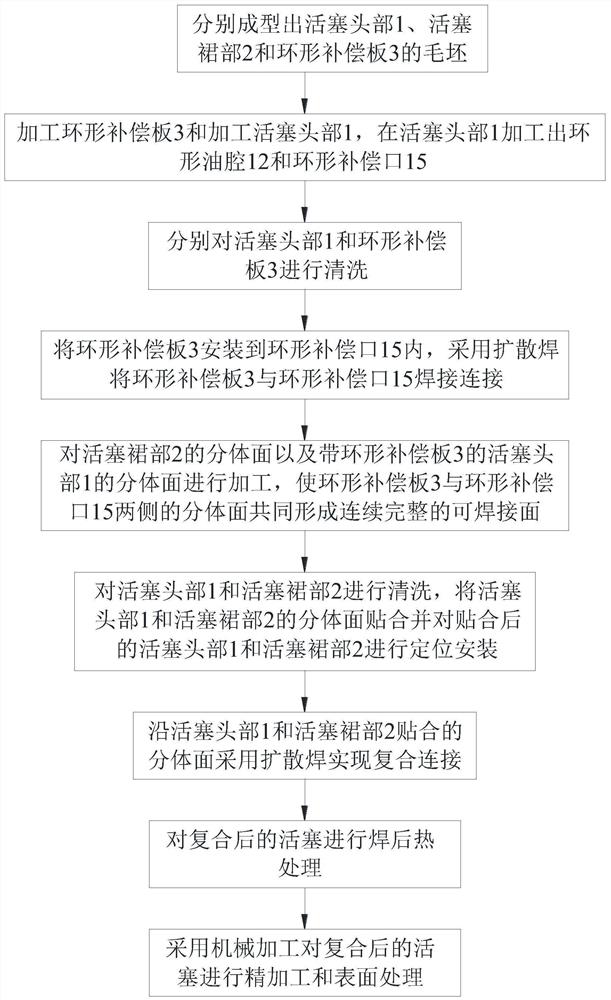
[0085] Figure 1 to Figure 3 Shown is the first embodiment of the split compound piston forming method of the present invention, the forming method includes the following steps:
[0086] S1: forming the blanks of piston head 1, piston skirt 2 and annular compensation plate 3 respectively;
[0087] S2: Process the annular compensation plate 3 and the piston head 1, and process the annular oil chamber 12 and the annular compensation port 15 on the piston head 1;
[0088] S3: cleaning the piston head 1 and the ann...
PUM
 Abstract
Description
Claims
Application Information
 - R&D
- Intellectual Property
- Life Sciences
- Materials
- Tech Scout
- Unparalleled Data Quality
- Higher Quality Content
- 60% Fewer Hallucinations
Browse by: Latest US Patents, China's latest patents, Technical Efficacy Thesaurus, Application Domain, Technology Topic, Popular Technical Reports.
© 2025 PatSnap. All rights reserved.Legal|Privacy policy|Modern Slavery Act Transparency Statement|Sitemap|About US| Contact US: help@patsnap.com


