A Low Dilution Ratio Double Filler Tig Overlay Welding Process and Its Application

A technology of dilution rate and wire filling, applied in the direction of manufacturing tools, welding equipment, arc welding equipment, etc., can solve the problems of reduced efficiency, increased welding equipment cost, large volume, etc., and achieve the effect of increased utilization

Active Publication Date: 2021-07-13
SHANDONG UNIV
View PDF7 Cites 0 Cited by
  • Summary
  • Abstract
  • Description
  • Claims
  • Application Information

AI Technical Summary

Problems solved by technology

However, this method needs to use an additional heat source to heat the welding wire, which significantly increases the cost of welding equipment; moreover, a conductive tip for heating the welding wire needs to be installed on the welding torch, resulting in a complicated structure and a large volume of the welding torch, which limits its flexibility and reliability. Reachability, not suitable for robot operation
In addition, the magnetic field generated by the hot wire current can easily lead to magnetic deflection, which affects the stability of the process.
More importantly, the inventors found that the increase of deposition speed and welding speed in hot wire TIG welding depends on the energy of the external heating wire power supply, and most of the energy of the arc is used to heat the workpiece, resulting in deep penetration of the workpiece Large, which in turn leads to a large dilution rate of the surfacing layer, and the surface of the workpiece usually requires 2 to 3 layers of surfacing to meet the requirements of use, which significantly increases the cost and reduces the efficiency of this process

Method used


Image

  • A Low Dilution Ratio Double Filler Tig Overlay Welding Process and Its Application
  • A Low Dilution Ratio Double Filler Tig Overlay Welding Process and Its Application
  • A Low Dilution Ratio Double Filler Tig Overlay Welding Process and Its Application

Examples


no. 1 example

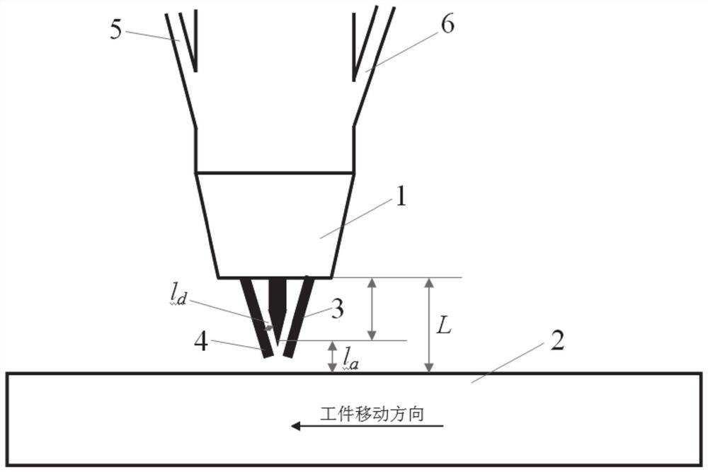
[0043] refer to figure 1 , a low-dilution rate double filler wire TIG surfacing process, including steps:

[0044] (1) Pre-treatment before welding: use 4mm thick low-carbon steel plate as the welding workpiece 2, clean the area to be surfacing and the surrounding area with a width of not less than 20mm, and remove oil stains and oxide films.

[0045] (2) Workpiece clamping: clamp the two workpieces processed in step (1) on a worktable capable of moving the workpiece at a constant speed at any speed between 0.1 and 3.0 m / min.

[0046] (3) Welding preparation: fix the welding torch on the upper part of the workpiece to be welded in step (2) according to the way that the two welding wires are arranged in front and back along the welding direction, and the vertical distance L between the nozzle 1 of the welding torch and the workpiece 2 is 7mm , the diameter of the welding wire is 1.2mm, the diameter of the tungsten pole is 3.2mm, the taper angle at the end is 40°, and the inclu...

no. 2 example

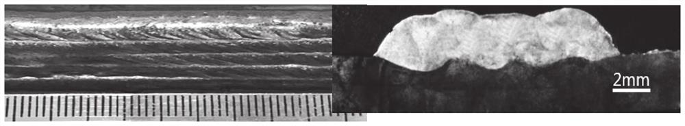
[0082] The same process as the first embodiment is used for surfacing welding. The purpose of this embodiment is to test the droplet transition and molten pool shape during the surfacing process of the workpiece. The results are as follows Figure 9 shown. It can be seen that the front and rear welding wires are all in contact transition, the molten pool under the arc continues to exist, the difference in the size of the molten droplet between the front and rear welding wires is small, and the molten droplet metal that alternately transitions into the molten pool quickly disperses into the molten pool, and the transition process and the molten pool are stable , The weld is well formed.

no. 3 example

[0088] refer to figure 1 , a low dilution rate double filler wire TIG surfacing process, including the following steps:

[0089] (1) Pre-welding pretreatment: use 6mm thick low-carbon steel plate as the welding workpiece 2, clean the area to be surfacing and the surrounding area of ​​not less than 20mm to remove oil stains and oxide films.

[0090] (2) Workpiece clamping: clamp the two workpieces processed in step (1) on a workbench capable of moving the workpiece at a constant speed at any speed between 0.1-3.0m / min.

[0091] (3) Welding preparation: fix the welding torch on the upper part of the workpiece to be welded in step (2) according to the way that the two welding wires are arranged in front and back along the welding direction. The vertical distance L between the nozzle 1 of the welding torch and the workpiece 2 is 9mm. The diameter of the tungsten pole is 1.2mm, the diameter of the tungsten pole is 3.2mm, the taper angle at the end is 40°, the angle between the two...


PUM

PropertyMeasurementUnit
thicknessaaaaaaaaaa
diameteraaaaaaaaaa
diameteraaaaaaaaaa

Abstract

The present invention relates to the technical field of TIG surface surfacing welding, in particular to a low dilution rate double filler wire TIG surfacing welding process and its application. The method includes: (1) pre-welding pretreatment: cleaning the area of ​​the workpiece to be welded with oil , Derusting. (2) Workpiece clamping: clamp the two workpieces processed in step (1) on a worktable that can move at a constant speed. (3) Welding: Use TIG welding torch with double feeding wire on the side wall of the nozzle, and arrange the welding torch on the upper part of the workpiece to be welded in such a way that the two welding wires are arranged in a row along the welding direction. The front and rear of the pool are surfacing. The surfacing welding process of the present invention properly matches the wire feeding speeds of the two welding wires according to the size of the welding current, reasonably distributes the arc heat between the welding wire and the workpiece, maximizes the melting amount of the welding wire and reduces the melting amount of the workpiece, and realizes a rate as low as 10-14%. Dilution rate, and deposition speed, welding speed, high utilization rate of arc energy.

Description

technical field [0001] The invention relates to the technical field of TIG surface overlay welding, in particular to a low dilution rate double filler wire TIG overlay welding process and its application. Background technique [0002] The information disclosed in this background section is only intended to increase the understanding of the general background of the present invention, and is not necessarily taken as an acknowledgment or any form of suggestion that the information constitutes the prior art already known to those skilled in the art. [0003] Surfacing welding, as an economical and rapid process method for surface modification of materials, is widely used in the manufacture and remanufacturing of parts in various industrial sectors. Common surfacing welding methods are tungsten argon arc (TIG) welding, submerged arc welding (SAW), strip electroslag welding, gas metal arc welding (GMAW), laser welding or electron beam welding. SAW surfacing, strip electroslag su...

Claims


Application Information

Patent Timeline
Patent Type & Authority Patents(China)
IPC IPC(8): B23K9/167B23K9/235B23K9/04
CPCB23K9/04B23K9/167B23K9/235
Inventor 陈茂爱周浩
Owner SHANDONG UNIV
Why Eureka
Try Eureka