Miniaturized magnetron structure

A magnetron and tube core technology, applied in the field of household microwave oven magnetron, can solve the problems of avoiding the use of ferrite magnetic rings, low temperature resistant permanent magnet materials, reducing the diameter and thickness of ferrite magnetic rings, etc. Achieve the effect of miniaturization design

Active Publication Date: 2020-10-02
UNIV OF ELECTRONICS SCI & TECH OF CHINA
View PDF12 Cites 2 Cited by
  • Summary
  • Abstract
  • Description
  • Claims
  • Application Information

AI Technical Summary

Problems solved by technology

[0004] At present, the structure of the common magnetron is as follows figure 1 As shown, it includes: bracket 1-1, base 1-2, tube core 1-3, heat dissipation blade 1-4, filter assembly 1-5, antenna 1-6 and permanent magnet (upper magnet 1-7, lower magnet 1 -8), wherein the base is square, the bracket is installed on the base to form a closed magnetic circuit, the upper magnet and the lower magnet are symmetrically arranged inside the bracket and the base up and down, the die is installed between the upper magnet and the lower magnet, and the heat dissipation blades are arranged Around the tube core, the filter assembly is arranged on the bracket and connected to the tube core, and the antenna is arranged under the base and connected to the tube core; the magnetic circuit system of the magnetron is mainly composed of ferrite permanent magnets, magnetic poles (tube core internal structure), the working gap formed by the relative magnetic poles, and the closed magnetic circuit formed by the peripheral bracket and the bottom plate; among them, although the ferr...

Method used


Image

  • Miniaturized magnetron structure
  • Miniaturized magnetron structure
  • Miniaturized magnetron structure

Examples


Embodiment Construction

[0025] The present invention will be described in further detail below in conjunction with the accompanying drawings and embodiments.

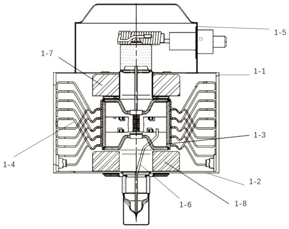
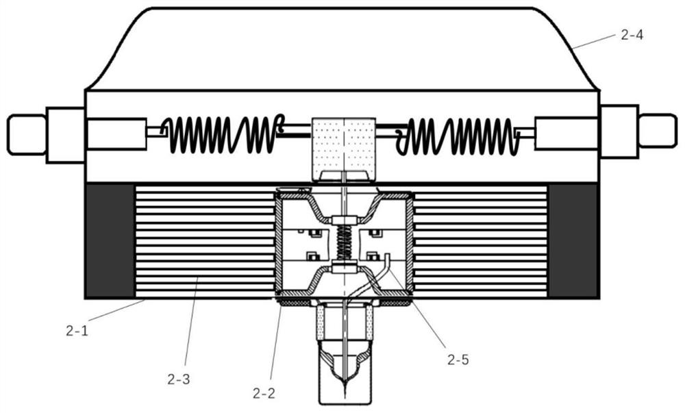
[0026] This embodiment provides a miniaturized magnetron structure, its structure is as follows image 3 As shown, it specifically includes: a bracket 2-1, a tube core 2-2, a heat dissipation blade 2-3, a filter assembly 2-4 and an antenna 2-5, wherein the tube core is installed in the center position of the bracket, and the heat dissipation The blades are arranged around the die, the filtering component is arranged on the support and connected to the die, and the antenna is arranged under the support and connected to the die;

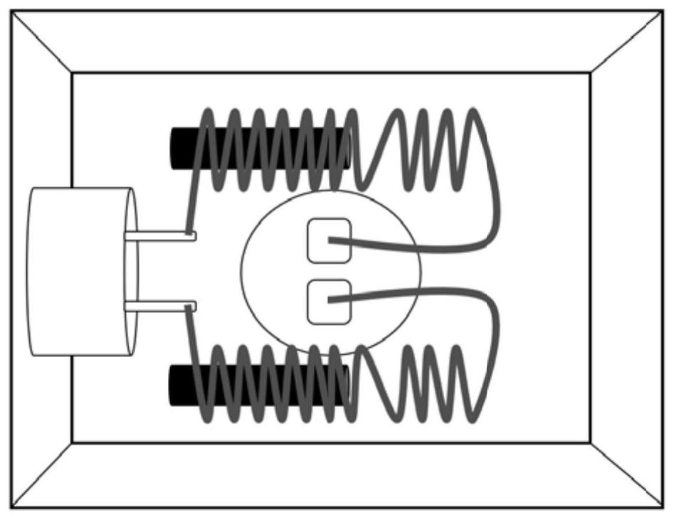
[0027] The support 2-1 is in the shape of a cuboid, such as Figure 4 As shown; surrounded by the top plate 2-1-1, the bottom plate 2-1-2, and the permanent magnet 2-1-3 fixedly supported between the top plate and the bottom plate, the permanent magnet is located in the short distance between the top plate and the bot...


PUM


Abstract

The invention belongs to the field of vacuum electronic devices, and particularly provides a miniaturized magnetron structure. According to the present invention, a neodymium iron boron or samarium cobalt permanent magnet material placed on an external support of a magnetron is adopted to replace an original ferrite magnetic ring so as to ensure the magnetic field intensity in an interaction space. The ferrite magnetic ring is not needed in the magnetron structure, and a neodymium iron boron or samarium cobalt permanent magnet is placed on the external support of the magnetron, so that the height and the width of the magnetron can be greatly reduced, and the magnetron structure is cuboid-shaped and can be matched with the shapes and the structures of the cooling fins and a filtering assembly synchronously, especially the filtering assembly. According to the invention, the output of an original same-direction choking coil from one end is improved into the output of a heterodromous choking coil from the left end and the right end, so that the miniaturized magnetron structure can stably work while being matched with a magnetic circuit structure. In conclusion, the invention provides the novel magnetron structure, and the miniaturization design of the magnetron structure is further realized.

Description

technical field [0001] The invention belongs to the field of vacuum electronic devices, and is mainly aimed at household microwave oven magnetrons, and proposes a new magnetron structure, a magnetic circuit system and a filter box structure, which effectively reduces the height and width of the magnetron, and further realizes the magnetron Control miniaturization. Background technique [0002] A microwave oven is mainly composed of a power supply, a magnetron, a control circuit, and a heating chamber. The power supply supplies high voltage to the magnetron, and the magnetron generates microwaves under the excitation of the power supply, and then transmits the microwaves to the heating chamber through a waveguide and an antenna. heating. The miniaturization of magnetrons has always been the main research direction of universities, enterprises, and research institutes, which not only improves the utilization rate, but also saves manufacturing costs. [0003] The magnetron is...

Claims


Application Information

Patent Timeline
IPC IPC(8): H01J23/087H01J23/00H01J23/15H01J25/50
CPCH01J23/005H01J23/087H01J23/15H01J25/50
Inventor 李海龙何其伟殷勇王彬蒙林朱逸政
Owner UNIV OF ELECTRONICS SCI & TECH OF CHINA
Why Eureka
Try Eureka