
Manufacturing method of new energy intelligent automobile printed circuit board

A technology for printed circuit boards and smart cars, which is applied in the fields of printed circuit manufacturing, laminated printed circuit boards, printed circuits, etc., and can solve problems such as back-drilling blockage, reducing the work efficiency of technicians, and restricting the development of new energy vehicles. Achieve the effect of reducing the possibility of blocking and improving efficiency

Active Publication Date: 2020-10-02
JIAN MANKUN TECH
View PDF5 Cites 0 Cited by
  • Summary
  • Abstract
  • Description
  • Claims
  • Application Information

AI Technical Summary

Problems solved by technology

[0003] From the perspective of the development of global new energy vehicles, the power sources of new energy vehicles mainly include lithium-ion batteries, nickel-metal hydride batteries, lead-acid batteries, and supercapacitors, among which supercapacitors mostly appear in the form of auxiliary power sources, mainly because these batteries The technology is not yet fully mature or has obvious shortcomings. Compared with traditional cars, there are many gaps in cost, power and cruising range. This is also an important reason restricting the development of new energy vehicles.
[0004] In the production process of printed circuit boards used in new energy vehicles, in order to improve production efficiency, manufacturers usually set the back drilling process before the solder mask process. However, due to the fast diffusion rate of solder mask ink, the ink is easy to contaminate the back drill holes It leads to the blockage of the back drill hole, so when applying the solder resist ink, the existing back drill hole is usually applied first, and the back drill hole is approached successively, thus greatly reducing the work efficiency of the technician

Method used


Image

  • Manufacturing method of new energy intelligent automobile printed circuit board
  • Manufacturing method of new energy intelligent automobile printed circuit board
  • Manufacturing method of new energy intelligent automobile printed circuit board

Examples


Embodiment 1

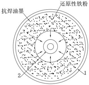
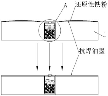
[0043] see Figure 1-2 A method for manufacturing a printed circuit board of a new energy smart car, comprising a printed circuit board 1, the upper end of the printed circuit board 1 being drilled with a back-drilled hole 2, comprising the following steps:

[0044] S1. Stack a plurality of core boards in sequence, press the plurality of core boards into a printed circuit board 1 by means of a punching device, and drill back-drilled holes 2 on the printed circuit board through a drilling device;

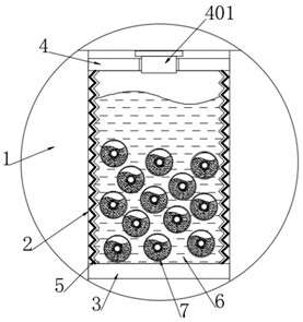
[0045] S2. Place the printed circuit board 1 after the back-drilled hole 2 is drilled on the workbench, add reducing iron powder to the solder resist ink and stir evenly, and then add an ink traction device to the back-drilled hole 2;

[0046] S3. Put the solder resist ink added with reduced iron powder on the surface of the printed circuit board 1, and surround the coated solder resist ink layer around the back drill hole 2, and evenly absorb the solder resist ink to the back drill ...


PUM


Abstract

The invention discloses a manufacturing method of a new energy intelligent automobile printed circuit board, which belongs to the technical field of automobile production. According to the scheme, reductive iron powder reacts with air to generate heat, therefore, the temperature in the solid-liquid reaction ball is promoted to rise; expansion of the inner extrusion ball is used, the rubber sealingsheet can be ejected open, an aqueous solution is promoted to pass through the reaction communication hole and enter the outer metal ball frame; the aqueous solution reacts with calcium oxide powder,thus, heat is further improved, on one hand, the air pressure in the annular corrugated bag sleeve can be increased, therefore, the magnetic movable plate is pushed to move upwards, the annular corrugated bag sleeve is pulled to expand upwards, and the possibility of solder resist ink entering the back drilling hole is reduced; and on the other hand, by means of upward movement of the magnetic movable plate, ferroferric oxide powder generated after the reductive iron powder reacts with oxygen can be attracted, so that the solder resist ink is driven to spread towards the hole opening of the back drilling hole, and the solder resist ink is smeared more evenly.

Description

technical field [0001] The invention relates to the technical field of automobile production, and more specifically, relates to a method for manufacturing a printed circuit board of a new energy intelligent automobile. Background technique [0002] New energy vehicles refer to the use of unconventional vehicle fuels as power sources (or the use of conventional vehicle fuels and new vehicle power devices), and the comprehensive vehicle power control and advanced technology in driving, the formation of advanced technical principles, with Vehicles with new technology and new structure, new energy vehicles in a broad sense, also known as alternative fuel vehicles, including pure electric vehicles, fuel cell electric vehicles and other vehicles that use non-petroleum fuels, as well as hybrid electric vehicles, ethanol gasoline vehicles, etc. Vehicles using non-petroleum fuels, all existing new energy vehicles are included in this concept, and are specifically divided into six cat...

Claims


Application Information

Patent Timeline
IPC IPC(8): H05K3/00H05K3/42
CPCH05K3/00H05K3/0047H05K3/0058H05K3/42H05K2203/0214H05K2203/06
Inventor 欧阳小军张孝斌肖学慧
Owner JIAN MANKUN TECH
Learn More