
Temperature rise test loop of low-voltage complete switch equipment and test method thereof

A switchgear, low-voltage complete set of technology, applied in the field of low-voltage electrical equipment inspection and testing, can solve the problems of power pollution, large volume, huge workload, etc.

Pending Publication Date: 2020-10-23
南通市产品质量监督检验所
View PDF0 Cites 0 Cited by
  • Summary
  • Abstract
  • Description
  • Claims
  • Application Information

AI Technical Summary

Problems solved by technology

Since the large-capacity multi-magnetic circuit transformer is equipped with variable resistors or current regulators, the equipment is huge, heavy and inconvenient to move. It requires high laboratory space and occupies a large area, so it is impossible to perform simultaneous detection of multiple sets.
In addition, because the working current of all branch circuits is controlled by open loop, it will change with the fluctuation of grid voltage, the change of circuit impedance heating, the impedance change caused by the load itself heating and other factors.
Therefore, the test personnel must often check the current changes of each branch circuit and adjust the variable resistor or current regulator in time to make the current return to the preset value, which causes a huge workload and there are uncontrollable test parameters in the whole test process. risk
Large-capacity multi-magnetic circuit transformers work in low-voltage and high-current mode, a large amount of electric energy is consumed in the loop and variable resistors or current regulators, and a large amount of reactive power loss is also generated to feed back to the grid, causing electric energy pollution
It can be seen that the traditional mainstream test scheme has the disadvantages of heavy test equipment, complicated operation process, unstable test parameters, excessive work intensity of personnel, high test cost, and polluting the power grid.

Method used


Image

  • Temperature rise test loop of low-voltage complete switch equipment and test method thereof
  • Temperature rise test loop of low-voltage complete switch equipment and test method thereof

Examples


Embodiment Construction

[0026] The present invention will be described in further detail below in conjunction with the accompanying drawings and embodiments. It should be understood that the specific embodiments described here are only used to explain the present invention, not to limit the present invention.

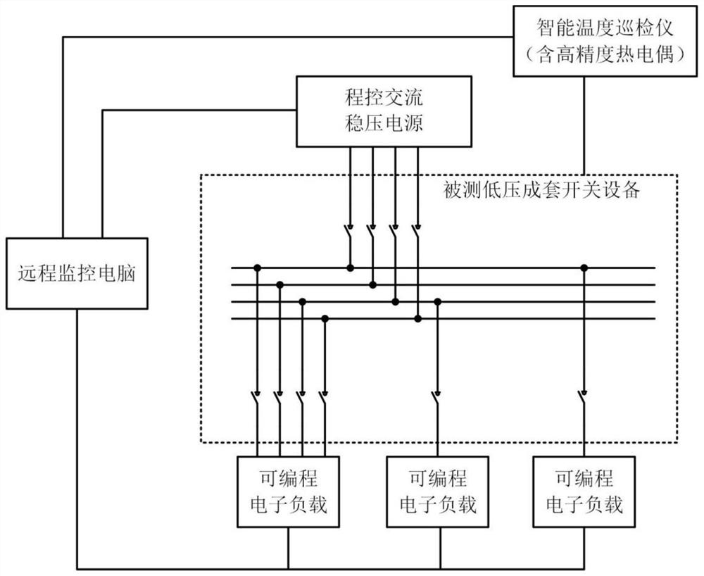
[0027] Such as figure 1 As shown, a low-voltage complete set of switchgear temperature rise test circuit, including a program-controlled AC power supply, intelligent temperature inspection instrument, a set of high-precision thermocouples, a set of programmable AC electronic loads, remote control computer, the measured low-voltage Complete set of switchgear, the output terminal of the program-controlled AC regulated power supply is connected to the main switch of the tested low-voltage complete set of switchgear, and each branch circuit of the tested low-voltage complete set of switchgear is connected to a programmable AC electronic load. The precision thermocouple is connected to the low-vol...


PUM


Abstract

The invention provides a temperature rise test loop of low-voltage complete switch equipment. The temperature rise test loop comprises a program-controlled alternating-current voltage-stabilized powersupply, an intelligent temperature itinerant detector, a group of high-precision thermocouples, a group of programmable alternating-current electronic loads, a remote control computer and tested low-voltage complete switch equipment. The beneficial effects of the invention are that a problem that manual real-time adjustment is needed due to changes of a power grid voltage and an impedance in a traditional test method is solved; the program-controlled alternating-current voltage-stabilized power supply and the programmable alternating-current electronic load are small in size, light in weightand stable in parameter, and can be remotely controlled; work intensity of testers is reduced; convenient operation is achieved, and test precision and stability are improved; and a method of inputting a current from a wire outlet end is not needed, requirements of national standards and an actual working condition of the tested low-voltage complete switch equipment are completely met, energy consumption of the program-controlled alternating-current voltage-stabilized power supply and the programmable alternating-current electronic load is very low, the energy consumption and cost of a temperature rise test are greatly reduced, a fault rate is low, and maintainability is good.

Description

technical field [0001] The invention belongs to the technical field of inspection and detection of low-voltage electrical equipment, and in particular relates to a temperature rise test circuit and a test method of a low-voltage complete switchgear, and is especially suitable for low-voltage complete switchgear in quality inspection institutes, certification inspection institutions and production enterprises at all levels. Conduct temperature rise experiments. Background technique [0002] The temperature rise test of low-voltage switchgear is particularly important and special among all type test items. According to the requirements of GB / T7251.1-2013 standard, the main circuit and all branch circuits of low-voltage switchgear must pass the rated current and measure the temperature at the same time. 1, the characteristics of this test are: the test time ranges from four or five hours to more than ten hours or even longer; the power consumption is huge, and the test cost is ...

Claims


Application Information

Patent Timeline
IPC IPC(8): G01R31/327G01R31/00G01R1/04
CPCG01R1/0416G01R31/003G01R31/3277
Inventor 黄海泉桂旭陈建豪张健唐勇张洁琳
Owner 南通市产品质量监督检验所
Learn More