Garbage pyrolysis and gasification incineration system and process

A technology of pyrolysis gasification and garbage, which is applied in the direction of incinerator, combustion type, combustion method, etc., can solve the problems of lowering the calorific value of garbage raw materials, no independent drying link, and large fluctuations in reaction temperature, so as to avoid incomplete reaction Full or even flameout, uniform and stable reaction, and improved utilization efficiency

Inactive Publication Date: 2020-10-30
山东百川同创能源有限公司
View PDF12 Cites 8 Cited by
  • Summary
  • Abstract
  • Description
  • Claims
  • Application Information

AI Technical Summary

Problems solved by technology

[0004] However, under the background of no large-scale promotion of classified collection and disposal of domestic waste or poor classification, the composition of domestic waste materials is complicated, the moisture content is high, and there is generally no independent drying process before incineration or pyrolysis gasification disposal. The moisture and the raw materials enter the flue gas after undergoing pyrolysis, gasification, combustion and other processes
Moisture lowers the calorific value of waste raw materials, affects the stable operation of the reactor, and is prone to unstable gas products, high residual organic matter content in ash, large fluctuations in reaction temperature, and even flameout
Generally, additional fuel such as fuel oil or gas is required to maintain the stable operation of the reactor and realize effective and environmentally friendly disposal of waste raw materials, but the operating cost is high
On the other hand, if the moisture in the garbage enters the flue gas, it will also cause problems such as high moisture content in the flue gas, corrosion of equipment, and difficulties in flue gas purification and treatment.

Method used


Image

  • Garbage pyrolysis and gasification incineration system and process

Examples


Embodiment 1

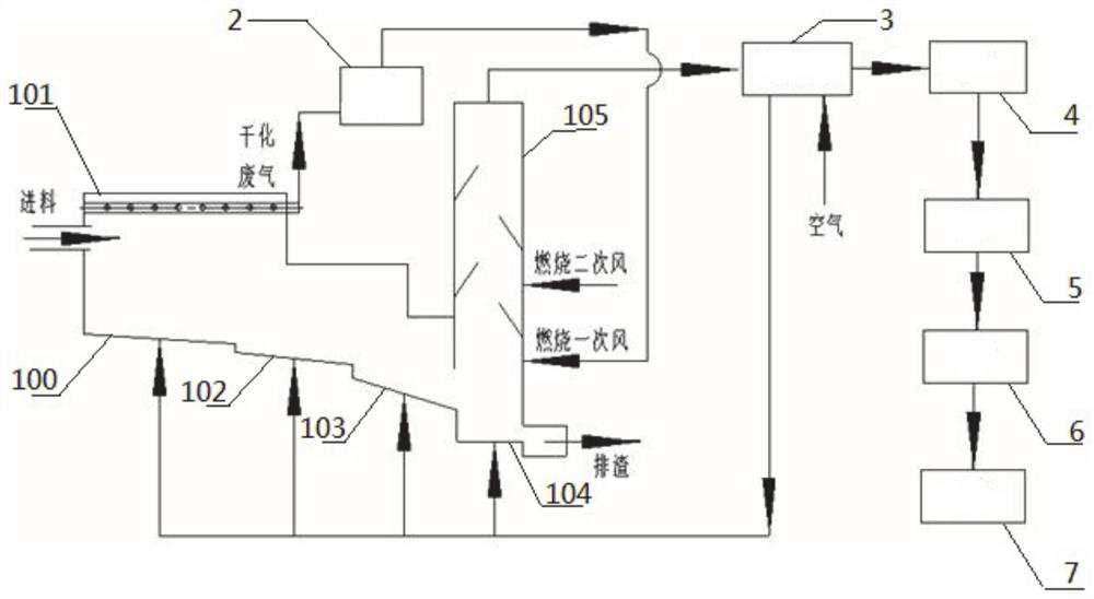
[0050] as attached figure 1 As shown, in this embodiment, a garbage pyrolysis gasification incineration system is provided. and the exhaust device are connected in sequence;

[0051] The pyrolysis gasification furnace has an integrally formed drying zone 100, pyrolysis zone 102, gasification zone 103, ash burnout zone 104 and gas combustion zone 105, wherein the drying zone 100, pyrolysis zone 102, gas The combustion zone 103 forms a stepped downward-sloping passage leading to the ash burnout zone 104, and the gas combustion zone 105 is located above the ash burnout zone 104;

[0052] A gas recovery pipeline 101 is arranged above the drying zone 100, and the gas recovery pipeline 101 leads to the gas combustion zone 105 after passing through the dehydration device; the top of the gas combustion zone 105 has a pipeline leading to a high-temperature heat exchanger, and the ash and slag There is a slag outlet at the bottom of the burnout zone for transferring the incinerated ga...

Embodiment 2

[0056] In this embodiment, a process for pyrolysis and incineration of waste based on the waste pyrolysis gasification incineration system described in Embodiment 1 is provided. The waste is fed through the feed port of the drying zone 100, and the The high temperature, the air distribution at the bottom of the furnace body, and the gas recovery pipeline 101 at the top of the drying area work together to extract the moist air from the garbage, reduce the moisture content of the garbage, and make it easier to ignite in the furnace without adding additional fuel . The dry exhaust gas containing water vapor is drawn out of the pyrolysis gasification combustion furnace through the negative pressure pipeline 101 with small holes provided on the upper part of the drying area 100, and is condensed and dehydrated by the dehydration device 2, and then sent back to the pyrolysis gasification combustion as the primary combustion air Furnace burning.

[0057] In the pyrolysis incinerator...


PUM


Abstract

The invention particularly relates to a garbage pyrolysis and gasification incineration system and process. According to the garbage pyrolysis and gasification incineration system, a pyrolysis and gasification furnace, a high-temperature heat exchanger, a quench tower, a demister, a dust collector and an exhausting device are connected successively, and the pyrolysis and gasification furnace is provided with a drying area, a pyrolysis area, a gasification area, an ash after-combustion area and a gas combustion area which are integrally formed. The drying area is further provided with an exhaust gas recovery pipeline to extract water vapor generated in a garbage drying process on the one hand to improve the stability of garbage pyrolysis and gasification and combustion reaction processes, and on the other hand, the dried exhaust gas can be further taken as primary combustion air of gas combustion. Heat generated by garbage incineration is distributed again to enter an incineration furnace to assist garbage combustion. The system can operate stably by controlling an air distribution proportion without extra energy for supporting combustion. A low generation rate of pollutants such asdioxin, heavy metals, oxynitride and oxysulfide can be further guaranteed. The garbage pyrolysis and gasification incineration system and process have good popularization and application value.

Description

technical field [0001] The invention belongs to the technical field of solid waste treatment, and in particular relates to a waste pyrolysis gasification incineration system and a waste incineration process using the system. Background technique [0002] The information disclosed in this background section is only intended to increase the understanding of the general background of the present invention, and is not necessarily taken as an acknowledgment or any form of suggestion that the information constitutes the prior art already known to those skilled in the art. [0003] At present, direct incineration and pyrolysis gasification incineration are the main ways to reduce the amount of domestic waste. Since waste raw materials are not convenient for long-distance transportation, and the investment and operating costs of incineration power generation projects are relatively high, it is not suitable for domestic waste to be incinerated for power generation alone in hilly, mou...

Claims


Application Information

Patent Timeline
Patent Type & Authority Applications(China)
IPC IPC(8): F23G5/027F23G5/04F23G5/44F23G5/46F23J15/02F23J15/04F23J15/06
CPCF23G5/006F23G5/04F23G5/027F23G5/44F23G5/46F23J15/06F23J15/022F23J15/04F23G2201/10F23G2201/302F23G2201/303F23G2206/10Y02E20/30
Inventor 董磊邹永才霍燕张屹常加富刘全美张兆玲
Owner 山东百川同创能源有限公司
Why Eureka
Try Eureka