Organic light-emitting device and display device

An electroluminescence device and electroluminescence technology, which are applied in electric solid devices, electrical components, semiconductor devices, etc., can solve the problems of low lifespan, high device operating voltage, serious dye carrier capture, etc., and achieve improved lifespan, The effect of reducing the operating voltage

Active Publication Date: 2020-10-30
KUNSHAN NEW FLAT PANEL DISPLAY TECH CENT
View PDF3 Cites 8 Cited by
  • Summary
  • Abstract
  • Description
  • Claims
  • Application Information

AI Technical Summary

Problems solved by technology

[0003] However, in TASF light-emitting devices, there are often serious problems of dye

Method used


Image

  • Organic light-emitting device and display device
  • Organic light-emitting device and display device
  • Organic light-emitting device and display device

Examples


preparation example Construction

[0096] The invention also provides a preparation method of the organic electroluminescence device, which comprises sequentially depositing an anode, a hole transport region, a light-emitting layer, an electron transport region and a cathode on a substrate, and then encapsulating. Wherein, when preparing the light-emitting layer, a multi-source co-evaporation method is used. The deposition methods of the anode, the hole transport region, the electron transport region and the cathode are the same as the existing methods in the art.

[0097] An embodiment of the present invention also provides a display device, which includes the organic electroluminescent device as provided above. Specifically, the display device may be a display device such as an OLED display, and any product or component having a display function such as a TV, a digital camera, a mobile phone, a tablet computer, etc. including the display device. The display device has the same advantages as that of the above...

Embodiment 1-11

[0099] Embodiment 1-11, comparative example 1

[0100] The above-mentioned embodiments and comparative examples respectively provide an organic electroluminescent device, and the preparation method is as follows:

[0101] (1) The glass plate coated with the ITO transparent conductive layer is ultrasonically treated in a commercial cleaning agent, rinsed in deionized water, ultrasonically degreased in acetone: ethanol mixed solvent, and baked in a clean environment until the water is completely removed , cleaning with UV light and ozone, and bombarding the surface with a beam of low-energy cations;

[0102] (2) Place the above-mentioned glass substrate with the anode in a vacuum chamber, and evacuate to less than 1×10 -5 Pa, vacuum-deposit HI-3 on the above-mentioned anode layer film as a hole injection layer, the evaporation rate is 0.1nm / s, and the evaporation film thickness is 2nm;

[0103] (3) The hole transport layer HT-28 is vacuum evaporated on the hole injection layer...


PUM


Abstract

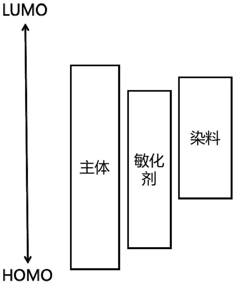
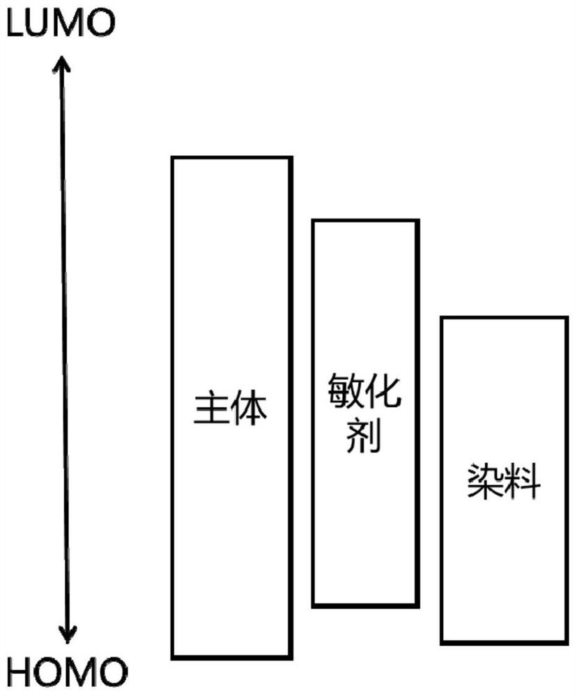
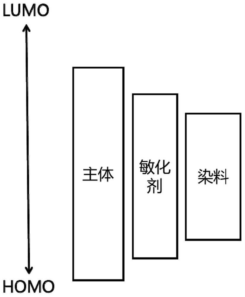
The invention relates to an organic light-emitting device and a display device. The organic light-emitting device comprises a first electrode, a second electrode and an organic layer located between the first electrode and the second electrode, wherein the organic layer comprises a light-emitting layer, the light-emitting layer contains a host material, a thermal activation delayed fluorescence sensitizer and a fluorescent dye, the energy level relationship between the main body material and the thermal activation delayed fluorescence sensitizer is shown in the specification, the LUMO main body is greater than or equal to the LUMO sensitizer, meanwhile, the HOMO sensitizer is greater than or equal to the HOMO main body, preferably, LUMO dye > LUMO sensitizer > HOMO dye > HOMO sensitizer isadopted, or the LUMO sensitizer > LUMO dye > HOMO sensitizer > HOMO dye, so the energy is completely transferred from the main body material to the sensitizer, but does not generate a relatively strong carrier capture problem with the dye. Therefore, the organic light-emitting device is advantaged in that the device voltage is reduced, and the service life of the device is prolonged.

Description

technical field [0001] The invention relates to the technical field of organic electroluminescence, in particular to an organic electroluminescence device and a display device. Background technique [0002] Thermally activated sensitized fluorescence (TASF) means that when thermally activated delayed fluorescence (TADF) materials are used as sensitizers, the energy of the host material is transferred to the TADF material, and then its triplet energy passes through the reverse intersystem crossing (RISC) The process returns to the singlet state, and then the energy is transferred to the doped fluorescent dye to emit light, which can realize the complete energy transfer from the host to the dye molecule, so that the traditional fluorescent doped dye can also break through the 25% internal quantum efficiency limit. [0003] However, in TASF light-emitting devices, there is often a serious problem of dye carrier capture, and the operating voltage of the device is high, and the l...

Claims


Application Information

Patent Timeline
IPC IPC(8): H01L51/50H01L51/54
CPCH10K85/624H10K85/622H10K85/636H10K85/626H10K85/633H10K85/631H10K85/615H10K85/654H10K85/6576H10K85/6574H10K85/657H10K85/40H10K50/121H10K50/11H10K2101/40H10K85/6572H10K2101/30H10K85/322H10K85/652H10K85/60
Inventor 李国孟席昭洋高孝裕李梦真孙磊徐超
Owner KUNSHAN NEW FLAT PANEL DISPLAY TECH CENT
Why Eureka
Try Eureka