Ultrathin flexible silicon solar cell

A silicon solar cell, flexible technology, applied in the direction of circuits, photovoltaic power generation, electrical components, etc., can solve the problems of large-scale industrialization, high production cost, and small bending arc, so as to improve the horizontal collection capacity and short-circuit current density , The effect of reducing resistance loss

Pending Publication Date: 2020-11-10
德运创鑫(北京)科技有限公司
View PDF0 Cites 0 Cited by
  • Summary
  • Abstract
  • Description
  • Claims
  • Application Information

AI Technical Summary

Problems solved by technology

[0004] However, the current mass-produced high-efficiency silicon solar cells weigh about 8-11g per sheet, that is, the weight per watt of the battery is 1.56-2.37g / W, which cannot be used in aerospace, stratospheric airships, and drones. , space station and other lightweight solar energy applications
Moreover, this kind of battery is generally a brittle product with a small bending arc, and it cannot be applied in the field of flexible solar energy.
[0005] Existing flexible solar cell technologies mainly include copper indium gallium selenide (CIGS) thin film components, cadmium telluride (CdTe) thin film components and gallium arsenide (GaAs) thin film components with flexible substrates (stainless steel or aluminum foil), among which CIGS and CdTe components The conversion efficiency is low, and the general mass production efficiency is 13-18%. Although the GaAs thin film module has a high efficiency, which can exceed 30%, its production cost is expensive and it cannot be industrialized on a large scale

Method used


Image

  • Ultrathin flexible silicon solar cell
  • Ultrathin flexible silicon solar cell
  • Ultrathin flexible silicon solar cell

Examples


Embodiment Construction

[0014] In order to make the purpose, technical solutions and advantages of the embodiments of the present invention more clear, the following will clearly and completely describe the technical solutions of the embodiments of the present invention in conjunction with the drawings of the embodiments of the present invention. Apparently, the described embodiments are some, not all, embodiments of the present invention. Based on the described embodiments of the present invention, all other embodiments obtained by persons of ordinary skill in the art without creative efforts shall fall within the protection scope of the present invention.

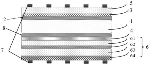
[0015] The application provides an ultra-thin flexible high-efficiency silicon battery. figure 1 It is a schematic diagram of the structure of this kind of ultra-thin flexible high-efficiency silicon battery, such as figure 1 As shown, the ultra-thin flexible silicon solar cell includes a transparent conductive layer 5, an n-type doped layer 3,...


PUM

PropertyMeasurementUnit
thicknessaaaaaaaaaa
thicknessaaaaaaaaaa
thicknessaaaaaaaaaa

Abstract

The invention relates to an ultrathin flexible silicon solar cell which comprises a transparent conductive layer, an n-type doped layer, a first intrinsic passivation layer, a monocrystalline siliconwafer, a second intrinsic passivation layer, a p-type doped layer and a semi-transparent and semi-reflective functional layer which are sequentially stacked, wherein the semi-transparent and semi-reflective functional layer comprises at least one TCO material layer and at least one metal layer. According to the ultrathin flexible silicon solar cell provided by the invention, by arranging the semi-transparent and semi-reflective functional layer, the short-wave transmittance is greater than 80%, the long-wave reflectivity is greater than 60%, the long-wave band light reaching the back surface of the silicon wafer is reflected and utilized again, and the short-circuit current density of the cell is improved. The semi-transparent and semi-reflective functional layer comprises a metal layer, so that the transverse collection capability of photo-generated holes on the back electrode is improved, the resistance loss is reduced, the FF of the cell is improved, and the flexible ultrathin silicon cell with the cell efficiency of 23.4% is finally obtained. The weight of the cell is 5.38 g, and the gram weight of each watt of cell is 0.95 g / W.

Description

[0001] This application claims the priority of the Chinese patent application with the application number 201910377312.7 and the title of the invention "An ultra-thin flexible silicon solar cell" filed with the State Intellectual Property Office of China on May 7, 2019, the entire contents of which are incorporated by reference in In this application. technical field [0002] The present application relates to the field of photovoltaic technology, in particular to an ultra-thin flexible silicon solar cell. Background technique [0003] At present, the vast majority of high-efficiency silicon solar cells in mass production use single or polycrystalline silicon wafers with a thickness of 150-200 μm, and the conversion efficiency of crystalline silicon cells is 19-21%, such as ordinary p-type crystalline silicon technology, p-type PERC (Passivated Emitterand Rear Cell, passivated emitter back surface cell) technology and n-type PERT (Passivated Emitter, RearTotally-diffused cel...

Claims


Application Information

Patent Timeline
Patent Type & Authority Applications(China)
IPC IPC(8): H01L31/0216H01L31/054H01L31/075H01L31/0445
CPCH01L31/02167H01L31/02168H01L31/075H01L31/0445H01L31/0547Y02E10/52Y02E10/548
Inventor 郁操徐希翔李沅民徐晓华
Owner 德运创鑫(北京)科技有限公司
Why Eureka
Try Eureka