Large-spacing phased-array antenna grating lobe suppression method and suppression system

A phased array antenna and large spacing technology, applied in the field of satellite communications, can solve problems such as weak local search ability, and achieve the effect of good grating lobe suppression effect and easy engineering realization.

Pending Publication Date: 2020-11-24
HEFEI RHOSOON INTELLIGENT TECH CO LTD
View PDF0 Cites 7 Cited by
  • Summary
  • Abstract
  • Description
  • Claims
  • Application Information

AI Technical Summary

Problems solved by technology

The algorithm itself has limitations. The genetic algorithm has a strong global search ability and can jump out of the loc

Method used


Image

  • Large-spacing phased-array antenna grating lobe suppression method and suppression system
  • Large-spacing phased-array antenna grating lobe suppression method and suppression system
  • Large-spacing phased-array antenna grating lobe suppression method and suppression system

Examples


Embodiment 1

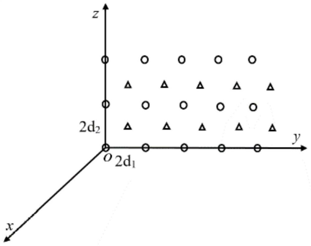
[0071] figure 1 A schematic diagram of the structure of the triangular grid array antenna is given, and there are M×N array elements in total. The antenna is located on the yoz plane, which can be regarded as the sum of two rectangular arrays, and the two sub-plane units are represented by circles and triangles respectively. The element spacing of these two arrays is 2d in the horizontal direction 1 , 2d in the vertical direction 2 . The pattern function for the entire array is:

[0072]

[0073] In the formula, is the comprehensive factor pattern of two planar antenna arrays arranged in rectangles; is the pattern of a planar phased array antenna with antenna elements arranged in a rectangle. This is the azimuth angle from the array to the target, and θ is the elevation angle from the array to the target. The maximum point of the main beam of the array is

[0074] Under constant omnidirectional conditions Can be expressed as:

[0075]

[0076] Can be ex...

Embodiment 2

[0105] Simulation and Analysis

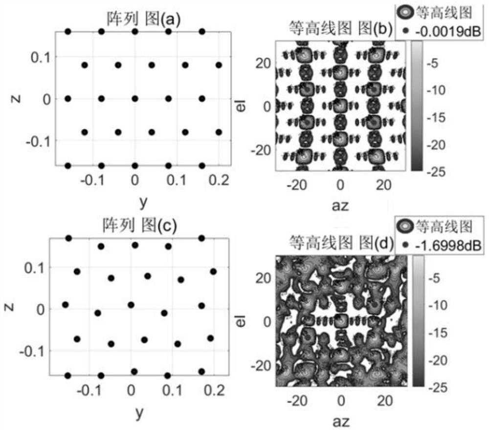
[0106] The antenna array model simulated and analyzed in this paper is a rectangular aperture antenna array arranged in a 5×5 triangular grid. The unit spacing is about 4 wavelengths. The unit amplitude distribution adopts the Taylor weight of -20dB, and the influence of amplitude and phase errors is not considered.

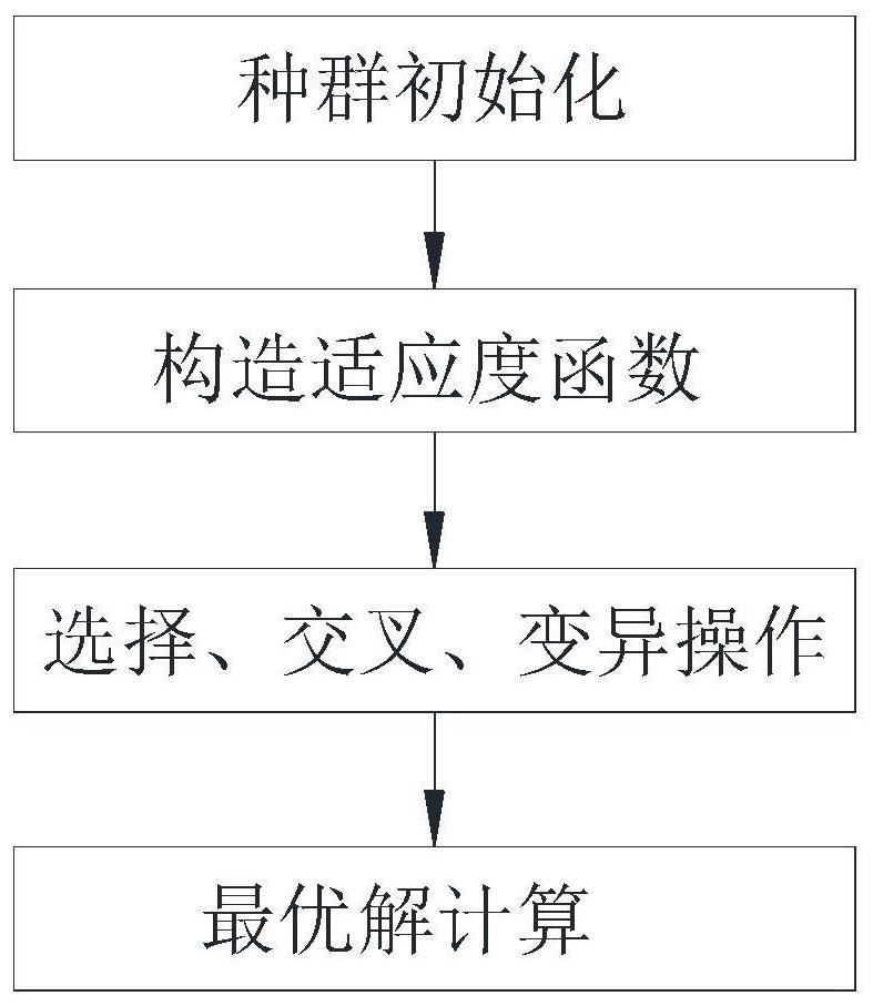
[0107] 1. Unconstrained array element position optimization simulation

[0108] The unconstrained optimization of the array element position refers to the random optimization of the position of the array element in the horizontal and pitch directions. Firstly, 1000 iterations are performed on 100 populations by genetic algorithm, and then the optimized array is re-optimized by pattern search algorithm. The array caliber is limited in the two optimization processes.

[0109] image 3 with Figure 4 is the array and its orientation pattern optimized by different optimization algorithms under the same optimization conditions. i...


PUM


Abstract

The invention provides a large-spacing phased-array antenna grating lobe suppression method. The method comprises the following steps: constraining the positions of array elements; constructing a fitness function and a fitness function optimization model; selecting and crossing: selecting a certain proportion of individuals before sorting as parents for generating a new generation of population; then performing crossover operation on the population of the generation to obtain a new generation of population; mutation: for each gene of each population, randomly generating a number r between [0,1], and if r is less than Pm, replacing r with a randomly generated parameter in a value domain, where Pm is a mutation probability; and optimal solution calculation: carrying out position optimization on the large-spacing planar array by utilizing a genetic algorithm, taking an optimization result as an initial solution of a mode search algorithm, and further optimizing to find an optimal solution under the current condition. The array obtained by constraining the positions of the array elements in the optimization process is easy to implement in engineering, the grating lobe suppression effect is good, and the grating lobe can be suppressed to-8dB or below under the condition that the minimum spacing of the array elements is 3 lambda.

Description

technical field [0001] The invention relates to the technical field of satellite communication, in particular to a method and system for suppressing grating lobes of a phased array antenna with large spacing. Background technique [0002] With the continuous development of satellite communication systems, the demand for ground terminal antennas is increasing, and the requirements for antenna gain are also increasing. Improving the gain of an active phased array antenna means increasing the aperture of the array and increasing the number of channels, which will increase the engineering cost, so designing a high-gain phased array antenna at a lower cost is of high engineering value. In general, reducing the number of array elements reasonably and appropriately increasing the spacing between array elements is an effective way to reduce the cost of the antenna. High grating lobes are bound to be generated when the array element spacing is higher than half a wavelength. Therefo...

Claims


Application Information

Patent Timeline
IPC IPC(8): G06F30/27G06N3/12
CPCG06N3/126
Inventor 桂文静邓庆勇桂万如林福江
Owner HEFEI RHOSOON INTELLIGENT TECH CO LTD
Why Eureka
Try Eureka