Power distribution network tail end electric energy router and control method thereof

A control method and technology of power distribution network, applied in the field of power supply system, can solve the problems of reduced system efficiency, large system size, complicated control, etc.

Pending Publication Date: 2020-12-11
HUNAN UNIV OF SCI & TECH
View PDF0 Cites 10 Cited by
  • Summary
  • Abstract
  • Description
  • Claims
  • Application Information

AI Technical Summary

Problems solved by technology

[0003] At present, the power routers researched at home and abroad are composed of multiple sub-modules of DAB structure, including high-frequency transformers. The system is large in size, heavy in weight, low in efficiency, and cannot realize multi-directional flow of power.
The existing power router topology and control methods cannot provide charging interfaces for new energy vehicles while using new energy to generate active power, and can also solve the problems of low voltage at the end of the line, low power factor, and three-phase power in rural distribution networks. Power quality problems such as unbalanced and high harmonic content, that is, the realization of power routing function, makes the promotion of the device difficult, the construction investment cost is high, and the later maintenance is difficult; Secondary power conversion, resulting in lower system efficiency and more complex control

Method used


Image

  • Power distribution network tail end electric energy router and control method thereof
  • Power distribution network tail end electric energy router and control method thereof
  • Power distribution network tail end electric energy router and control method thereof

Examples


Embodiment Construction

[0045] A preferred embodiment of the present invention will be described in detail below with reference to the accompanying drawings.

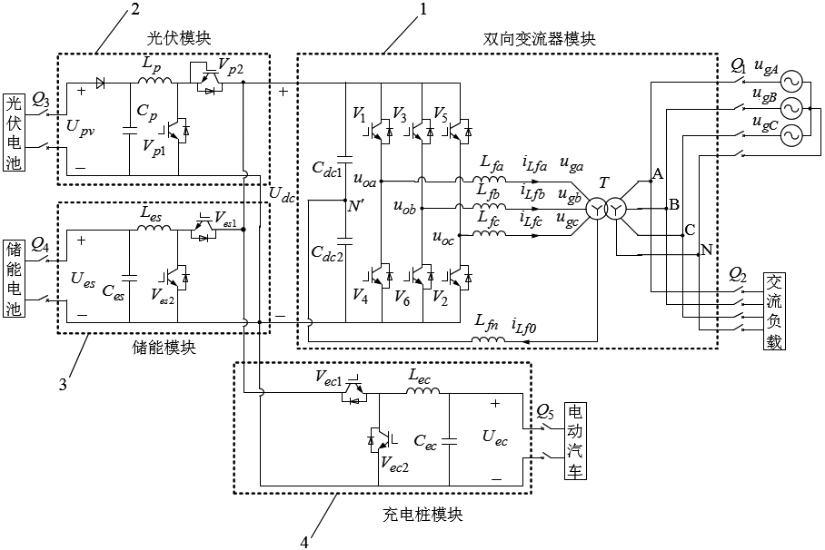
[0046] Such as figure 1 As shown, the topology of the power router at the end of the distribution network includes four parts: a bidirectional converter module 1 , a photovoltaic module 2 , an energy storage module 3 and a charging pile module 4 .

[0047] The bidirectional converter module 1 includes a three-phase four-wire capacitor split voltage inverter and a three-phase isolation transformer, the DC bus voltage U dc Obtained by three-phase four-wire capacitor split voltage inverter U ga , U gb , U gc , and then through the three-phase isolation transformer to obtain the three-phase alternating current of the distribution network U gA , U gB , U gC .

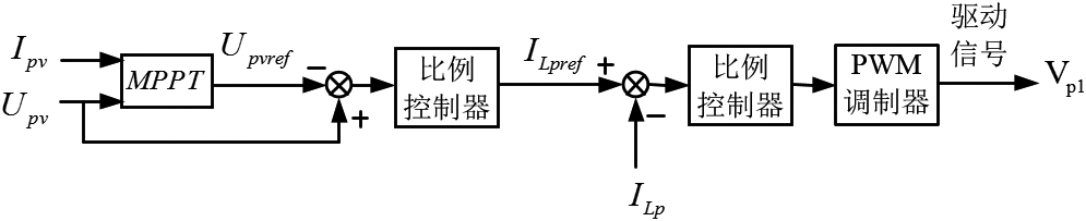
[0048] The photovoltaic module 2 includes a Boost circuit module. The Boost circuit is a common step-up conversion circuit. By controlling the power switch V p1 The turn-on ...


PUM


Abstract

The invention relates to the technical field of power supply systems, in particular to an electric energy router for the tail end of a power distribution network and a control method thereof. A bidirectional converter module is used for providing a power distribution network and an alternating-current load interface, realizing alternating-current and direct-current electric energy conversion and performing electric energy quality treatment on the power distribution network, and comprises reactive power compensation, harmonic wave compensation, negative-sequence current compensation and zero-sequence current compensation; a photovoltaic module is used for providing a photovoltaic cell interface and utilizing the electric energy generated by the photovoltaic cell to the maximum extent; an energy storage module is used for providing an energy storage battery interface to realize a peak clipping and valley filling function; and a charging pile module is used for providing a charging interface for the new energy automobile to realize a function of charging the new energy automobile. According to the invention, various forms of electric energy conversion can be realized, compared with the existing electric energy reason device, a high-frequency isolation transformer is not needed, the system volume is smaller, the mass is lighter, the efficiency is higher, and the structure is simpler.

Description

technical field [0001] The invention relates to the technical field of power supply systems, in particular to a power router used at the end of a distribution network and a control method thereof. Background technique [0002] In recent years, in order to solve the energy crisis and reduce environmental pollution, distributed renewable energy has been vigorously developed. Macroscopically, the "new infrastructure" policy was proposed, emphasizing the transformation of rural power grids and the construction of new energy vehicle charging piles. Microscopically, the number of household appliances in rural areas in my country is increasing, but the rural distribution network is weak, which leads to problems such as low voltage at the end of the line, low power factor, unbalanced three-phase and large harmonic content in the distribution network system. Therefore, from the perspective of giving full play to the geographical advantages of rural areas with large land and sparse p...

Claims


Application Information

Patent Timeline
Patent Type & Authority Applications(China)
IPC IPC(8): H02J3/48H02J3/32B60L58/12B60L53/62H02M3/155H02M7/797H02M1/08
CPCB60L53/62B60L58/12H02J3/32H02J3/48H02M1/08H02M3/155H02M7/797H02J2300/22Y02E70/30Y02T10/70Y02T10/7072Y02T10/72Y02T90/12
Inventor 肖华根曹可刘晨
Owner HUNAN UNIV OF SCI & TECH
Why Eureka
Try Eureka