Stepless speed regulator based on differential transmission/power converging mechanism, and energy-saving system thereof

A technology of differential transmission and stepless speed regulation, which is applied in the direction of differential transmission, transmission, and mechanical energy control. The effect of permanent, easy and low-cost energy-saving retrofit

Pending Publication Date: 2020-12-15
林贵生
View PDF0 Cites 6 Cited by
  • Summary
  • Abstract
  • Description
  • Claims
  • Application Information

AI Technical Summary

Problems solved by technology

Since 2009, the inventor has successively obtained more than ten invention patents on permanent magnetic coupling speed regulators, and has built a factory with self-raised funds, forming mass production. Energy saving and emission reduction has been widely used and praised, which has greatly improved the level of energy saving technology. However, during the promotion process, it gradually realized that permanent magnetic coupling speed regulators have many advantages, but there are also the following shortcomings that are difficult to overcome: 1. Because the active and passive disks are air gap coupled cantilever beam structures, and are limited by the design of the axial installation size of the equipment, severe vibration and noise will inevitably occur under high power or / and high speed conditions, resulting in reliable system The second is that the system efficiency is low, especially under the conditions of low rated speed, high power, and more speed reduction, the energy proportional to the percentage of speed reduction will become a large amount of heat and be consumed in the metal conductor disk In fact, the average actual working total useful efficiency of the power load system is generally lower than 60%, especially for high-power models, because the system needs to add cooling devices, the cost will increase accordingly, and the reliability will also be greatly reduced; the third is It can only be adjusted by reducing the speed, but not by increasing the speed; fourth, the accuracy of speed adjustment is relatively low; fifth, there is no torque conversion or self-locking function between the active (power) shaft and the passive (load) shaft, so the application is greatly limited
[0003] High-voltage and high-power motor inverters also have many applications in the field of energy saving and emission reduction of centrifugal load systems. However, due to high requirements on the operating environment (constant temperature and humidity), they occupy a large space, have poor reliability, and consume a lot of energy; due to their working efficiency characteristics Constraints make the average actual total useful efficiency of the power load system in most frequency bands significantly lower than the rated efficiency, generally lower than 60%; the inverter will also produce serious power harmonic pollution, and the high-voltage inverter equipment is expensive, requiring There are many shortcomings such as dedicated maintenance and huge operating costs, which are also widely criticized
[0004] Hydraulic coupling governors are also widely configured in adjustable centrifugal load and non-centrifugal load systems (such as fans, water pumps, ball mills, feeders, conveyor belt conveyors, roadheaders, drilling machines, elevators, air compressors, etc.) , because the average actual working efficiency of the power load system is relatively low, and its speed regulation range is small, the consumption of hydraulic media consumables is large and the environment is polluted, etc., the technology is even more backward
[0005] For the traditional speed governor energy-saving technology mentioned above, on the one hand, it is only applicable to the "big horse-drawn trolley" system, which is not conducive to improving system efficiency and causing waste of resource allocation; During the adjustment process, only the power consumed by the load can be reduced, and the output efficiency of the power system cannot be improved. It will also cause the power system to greatly reduce the working efficiency, causing serious energy consumption and heat generation in the system. This heat is not only difficult to recycle, but also needs to be equipped with the system. Cooling device, while greatly increasing the cost input, the system reliability is also significantly reduced
In other words, for the current large-scale power load system, especially centrifugal equipment such as large fans and pumps, even if energy-saving equipment such as frequency converters, permanent magnet governors, and hydraulic couplings are installed, the average actual work of the power load system The total useful efficiency is generally not more than 65%, or even lower, and the waste is huge
In addition, due to the matching problem of power and load in the common power and load system, it will also cause serious energy or power waste.

Method used


Image

  • Stepless speed regulator based on differential transmission/power converging mechanism, and energy-saving system thereof
  • Stepless speed regulator based on differential transmission/power converging mechanism, and energy-saving system thereof
  • Stepless speed regulator based on differential transmission/power converging mechanism, and energy-saving system thereof

Examples


Embodiment 1

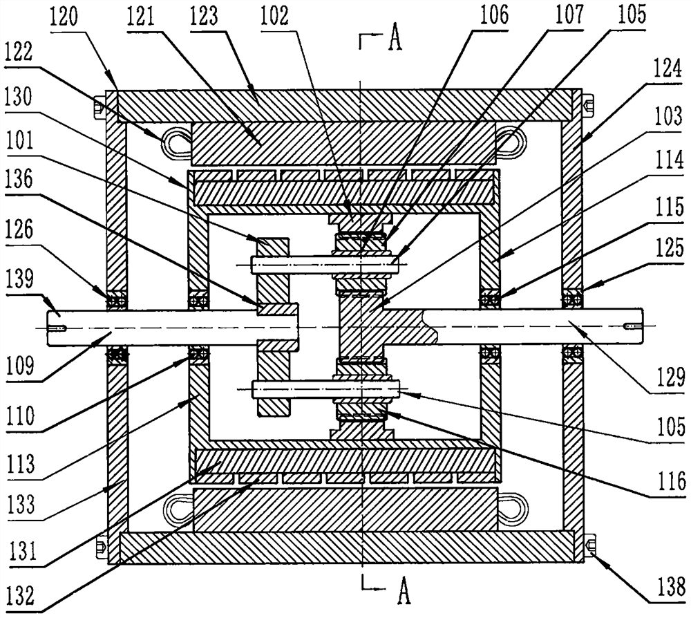
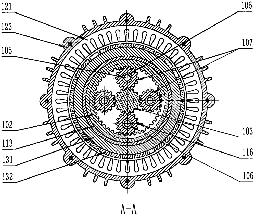
[0045] Such as figure 1 and figure 2As shown, it is a stepless speed governor based on a differential transmission / power confluence mechanism, and it is an embedded stepless speed governor based on an asymmetric axial cylindrical planetary gear differential transmission / power confluence mechanism. Asymmetric axial cylindrical planetary gear differential transmission / power converging mechanism (differential transmission / power converging mechanism is used in some common technical fields such as the automotive field, or is called differential, differential machine, in the field of transmission technology Or known as power splitter, power splitter, power converging mechanism, power splitting mechanism, etc., they have different or different structures in different application fields, but the working mechanism is similar) The components are embedded and set in the power regulation / speed regulation In the hollow rotor of the motor, it mainly consists of four axial cylindrical plan...

Embodiment 2

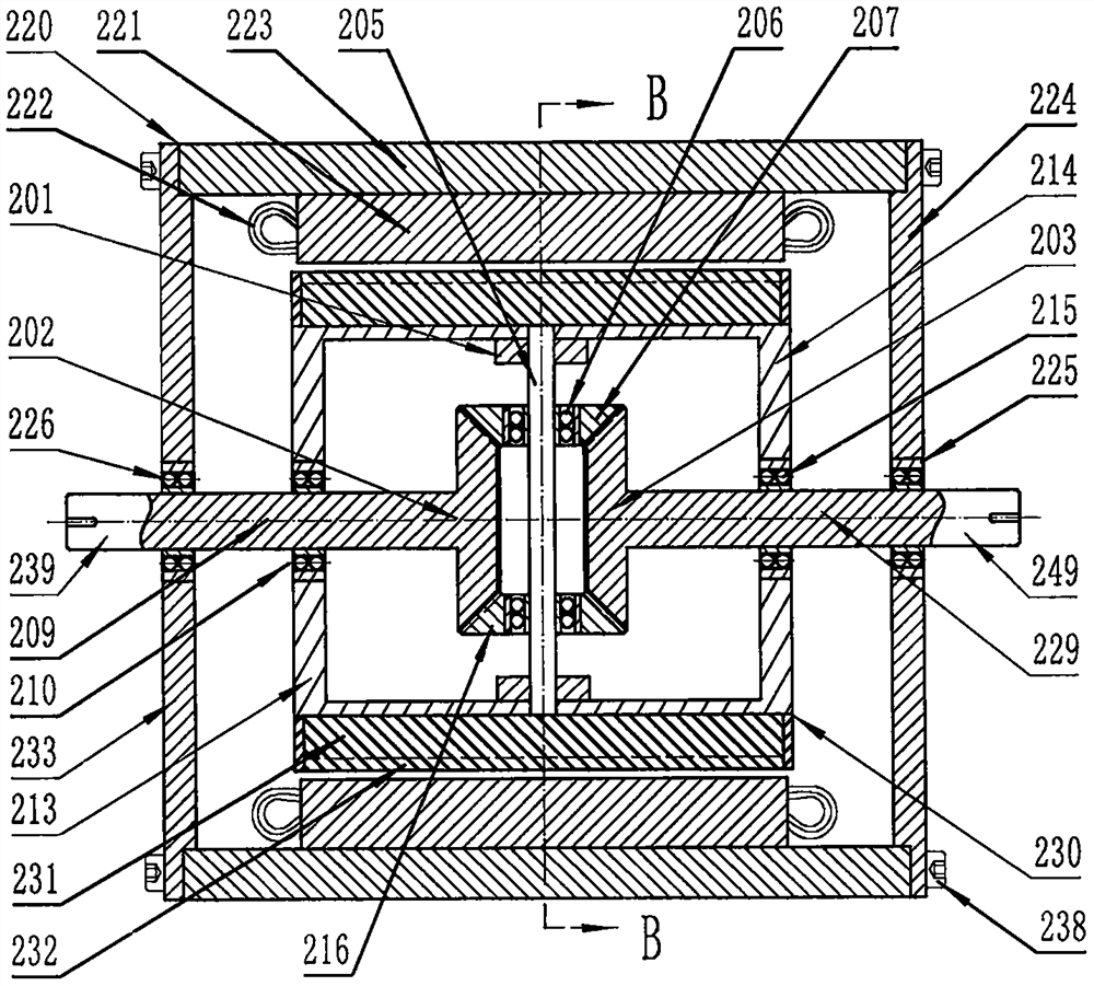
[0052] Such as image 3 and Figure 4 As shown, it is a stepless speed governor based on a differential transmission / power confluence mechanism, and it is an embedded stepless speed governor based on a symmetrical radial conical planetary gear differential transmission / power confluence mechanism. The differential transmission / power converging mechanism assembly is integrally embedded in the hollow rotor of the power adjustment / speed regulating motor, and it is mainly composed of radial conical planetary gears (207 and 216) differential transmission / power converging mechanism assembly (201, 202, 203 , 205, 206, 207, and 216), the stator (220, 221, 222, 223, 224, and 233) and the hollow rotor (230, 231, 232, 213, and 214) of the power regulation / speed regulating motor, based on the differential transmission Other accessories (226, 210, 215, 225 and 238) of the stepless speed governor of the power converging mechanism, a motor / generator duplex controller and a state sensor (not ...

Embodiment 3

[0057] Such as Figure 5 As shown, it is a stepless speed governor based on differential transmission / power confluence mechanism, which is an embedded stepless speed regulator based on asymmetrical axial double-ended circular planetary gear differential transmission / power confluence mechanism. accelerator. It is configured with a power regulation / speed regulation motor (320) to control a drive / frequency converter and a state sensor assembly (not shown), an asymmetrical axial double-ended circular planetary gear differential transmission / power converging machine assembly (301, 302 , 303, 305, 306, 307, 345, 356 and 316) are integrally embedded in the hollow rotor (330) of the squirrel-cage AC asynchronous power regulation / speed regulation motor (320), and the right half shaft (329) is the power output The end / shaft is set as the right half rotor shaft (329) of the hollow rotor shaft system (329) of the power regulation / speed regulation motor (320) through the correspondingly a...


PUM


Abstract

The invention discloses a stepless speed regulator based on a differential transmission / power converging mechanism, and an energy-saving system thereof. The stepless speed regulator based on the differential transmission / power converging mechanism is mainly composed of a differential transmission / power converging mechanism assembly, a power regulation / speed regulation motor, a motor control driverand a speed regulator accessory, wherein the differential transmission / power converging mechanism assembly comprises a planet gear carrier, a planet gear, a planet gear shaft, a left half shaft gearand a right half shaft gear, and the planet gear is mutually meshed with at least one pair of left half shaft gear and right half shaft gear separately; and the left half shaft, the right half shaft and the planet gear carrier are used as a power output end / shaft, a power regulation end / shaft and a power input end / shaft of the stepless speed regulator separately. The stepless speed regulator basedon the differential transmission / power converging mechanism is compact in structure, excellent in performance, low in noise and vibration, super-high in efficiency, suitable for working conditions ofhigh, medium and low rotating speeds, large and medium power and severe environments, more beneficial to automation and intelligence of a power load system, capable of constructing a speed regulationenergy-saving system according to the energy-saving concept of 'doing with full power, consuming less in the case of sufficient supply, and recovering in the case of excess', or constructing load power configuration according to the energy-saving concept of 'force measurement, required amount and no waste', and capable of providing perfect stepless speed regulation super energy-saving system technical support for various power load equipment application scenes.

Description

technical field [0001] The present invention relates to stepless speed governors, power dividing / combining devices, dual-way / multi-stage power allocation in rotating power and its load systems (such as fans, pumps, various transportation vehicles, and various mechanical equipment, etc.) In the technical field of stepless speed regulation and power load adaptation such as devices and energy recovery devices, it relates to a device with many functions such as stepless speed regulation, torque conversion, energy recovery, power mixing, distributed power configuration, and stepless power allocation. A power regulator / governor with some functions or all functions in one and its super energy-saving system, especially a stepless speed governor based on a differential transmission / power converging mechanism and its energy-saving system. Background technique [0002] In the past ten years, the rapidly developed permanent magnet coupling governor has gradually been recognized by exper...

Claims


Application Information

Patent Timeline
Patent Type & Authority Applications(China)
IPC IPC(8): F16H3/44F16H3/76F16H48/06F16H48/38H02K7/116F16H57/028
CPCF16H3/44F16H3/76F16H48/06F16H48/38F16H57/028H02K7/116
Inventor 林贵生
Owner 林贵生
Why Eureka
Try Eureka