Magnetoelectric data trigger triggered by magnetic field and implementation method thereof

An implementation method and trigger technology, applied in the application of electromagnetic devices to generate pulses, electric pulse generator circuits, etc., can solve the problems of wiring redundancy, large size, circuit loss response time, etc., and achieve simple wiring and fast response. , the effect of low loss

Active Publication Date: 2020-12-15
ZHENGZHOU UNIVERSITY OF LIGHT INDUSTRY
View PDF7 Cites 2 Cited by
  • Summary
  • Abstract
  • Description
  • Claims
  • Application Information

AI Technical Summary

Problems solved by technology

[0004] Aiming at the technical problems of current traditional D flip-flop wiring redundancy, large volume, serious circuit loss and long response time, the present invention proposes a magnetic-electric data flip-flop triggered by a magnetic field

Method used


Image

  • Magnetoelectric data trigger triggered by magnetic field and implementation method thereof
  • Magnetoelectric data trigger triggered by magnetic field and implementation method thereof
  • Magnetoelectric data trigger triggered by magnetic field and implementation method thereof

Examples


Embodiment 1

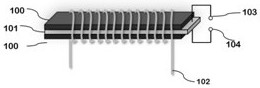
[0030] Embodiment 1: as figure 1 As shown, a magnetoelectric data trigger using a magnetic field trigger includes two layers of ferromagnetic elements 100, a piezoelectric element 101 is arranged between the two layers of ferromagnetic elements 100, and the size of the specifically used rectangular ferromagnetic element 100 is 38mm × 5mm × 0.5mm, the size of the rectangular piezoelectric element 101 is 40mm × 5mm × 0.5mm, the shape of the ferromagnetic element and the piezoelectric element are both rectangular, and the material of the rectangular ferromagnetic element is nickel-zinc ferrite material, nickel-zinc The chemical equation of the ferrite material is Ni0.8Zn0.2Fe2O4, the material of the piezoelectric element is piezoelectric ceramic PZT-8, the piezoelectric element is polarized along the thickness direction, the rectangular ferromagnetic element and the piezoelectric element The thickness is consistent with the width, and the length of the piezoelectric element is sl...

Embodiment 2

[0033] Embodiment 2: A method for implementing a magnetoelectric data trigger triggered by a magnetic field, comprising the following steps:

[0034] S1. When testing the magnetoelectric data trigger, select the sample of the magnetoelectric data trigger, lock-in amplifier, multimeter, vibration sample tester and electromagnet, the electromagnet is used as the bias magnetic field source, and the sample of the magnetoelectric data trigger The upper wire 103 and the lower wire 104 of the output port are connected to the lock-in amplifier, and the magnetoelectric voltage signal output by the output port of the magnetoelectric data trigger is detected by the lock-in amplifier; when testing, at first the AC magnetic field source and the bias magnetic field source are passed into The current causes the two layers of ferromagnetic element layer and piezoelectric element layer to produce magnetostrictive effect and piezoelectric effect, and at this time, the wire drawn from the piezoel...


PUM

PropertyMeasurementUnit
strengthaaaaaaaaaa

Abstract

The invention provides a magnetoelectric data trigger triggered by a magnetic field and an implementation method thereof. The magnetoelectric data trigger comprises three layers of magnetoelectric heterojunctions and copper coils uniformly wound on the peripheries of the heterojunctions, and magnetic field pulse trigger signals are provided by electromagnets applied to two ends of the rectangularmagnetoelectric heterojunctions. Magnetization of different degrees is generated by controlling a bias magnetic field to induce a magnetostriction phase through the magnetoelectric effect, so that thedynamic magnetomechanical strain of the magnetoelectric heterojunctions is regulated and controlled, and the output voltage maintaining and converting functions are achieved by changing the directionand residual magnetism occurring in the bias magnetic field under the excitation of an alternating magnetic field. Therefore, the ferroelectric layers of the magnetoelectric heterojunctions generatenonvolatile voltage and cause the change of the output high / low level state, thereby realizing the tracking and maintaining functions of classic data triggering. Compared with a traditional D trigger,the magnetoelectric data trigger has the remarkable advantages of being low in loss, quick in response, simple in wiring and the like, and can replace the traditional D trigger and be applied to a modern digital system.

Description

technical field [0001] The present invention relates to the technical field of D flip-flops, in particular to a magnetoelectric data flip-flop triggered by a magnetic field and a realization method thereof. Background technique [0002] Data flip-flop (D flip-flop) is an information storage device with memory function and bistable state transition. It is used in the design of modern large-scale digital integrated circuits, especially in synchronous sequential integrated circuits, clock frequency division, data latch An important logic unit circuit in a design. D flip-flops are widely used in digital systems and computer systems, and can be used as logic function devices such as digital signal registration, shift registration, frequency division, waveform generation, and counting. [0003] The existing D flip-flop is composed of many gate circuits or many transistor circuits, but the transistors prepared by the existing CMOS technology have leakage current and channel effect...

Claims


Application Information

Patent Timeline
Patent Type & Authority Applications(China)
IPC IPC(8): H03K3/59
CPCH03K3/59
Inventor 张吉涛李康张庆芳赵艺芳陶加贵武洁曹玲芝
Owner ZHENGZHOU UNIVERSITY OF LIGHT INDUSTRY
Why Eureka
Try Eureka