
Novel film-coated plugging disc

A blocking disk and film-covering technology, which is applied in the field of medical devices, can solve the problems that the blocking disk and flow-blocking film cannot be completely covered, the thickness of the film cannot be too thick, and the sealing is not complete, so as to achieve controllability and Fully repeatable recyclability, avoiding direct contact, and reducing frictional resistance

Pending Publication Date: 2020-12-18
NINGBO DIOCHANGE MEDICAL TECH CO LTD
View PDF4 Cites 1 Cited by
  • Summary
  • Abstract
  • Description
  • Claims
  • Application Information

AI Technical Summary

Problems solved by technology

Therefore, when this type of occlusion disk is placed at the mouth of the LAA or the cavity of the LAA, the occlusion disk and the blocking membrane cannot completely cover the opening of the LAA or cannot completely fit the cavity of the LAA, which eventually leads to The probability of residual shunt is greatly increased, even leading to the failure of plugging
[0008] (3) Some researchers have proposed a palliative design, that is, the expanded polytetrafluoroethylene film is used to plug the occluder, and its peripheral edge is covered with the inner and outer walls of the braided wire by thermal fusion and bonding. To avoid the defects caused by suture connection in the prior art, however, because the occluder needs to be delivered through interventional surgery, it is required that the connection between the membrane and the occluder needs to adapt to the huge deformation of the occluder shape, so this design It is only applicable to a very small range on the peripheral surface of the occluder disc, and usually does not exceed the length of a braided mesh (≤4mm) in the braided design of the conventional occluder, and the sheath used in the interventional operation of the occluder is usually not larger than 14F, so the thickness of the film used cannot be too thick (usually no more than 0.2mm), which is similar to the above-mentioned planar flow blocking film in essence, so the plugging performance brought by this design also exists in the above-mentioned planar shape barrier film defects
[0009] (4) Patent No.: CN201720115376.6 left atrial appendage occluder and LAmbre left atrial appendage occluder occluder plate is in the shape of a sheet with sharp edges and can only be placed on the outer edge of the mouth of the left atrial appendage. Beating will wear the tissues around the left atrial appendage, such as mitral valve, left upper pulmonary vein, etc., and eventually lead to complications such as myocardial perforation, bleeding, and inflammation
[0010] (5) The existing occlusion disc is formed by alternately weaving nickel-titanium alloy wires up and down, and the wires are restrained by each other. It is difficult to adapt to the irregular opening of the left atrial appendage, and it is easy to cause residual shunt
[0011] Therefore, it is an important research direction to provide a new type of film-coated occlusion disc, which can solve a series of problems in the prior art, such as complications caused by device wear tissue, incomplete occlusion, and poor biocompatibility.

Method used


Image

  • Novel film-coated plugging disc
  • Novel film-coated plugging disc
  • Novel film-coated plugging disc

Examples


Embodiment 1

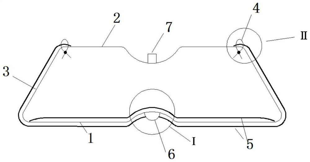
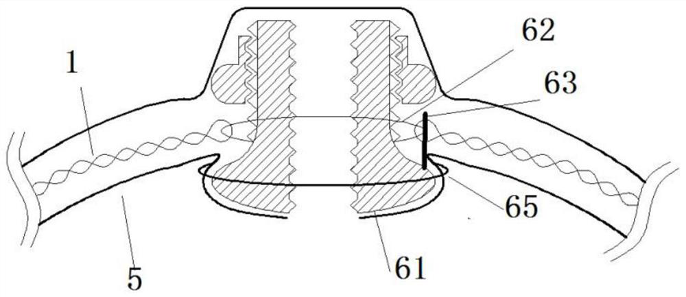
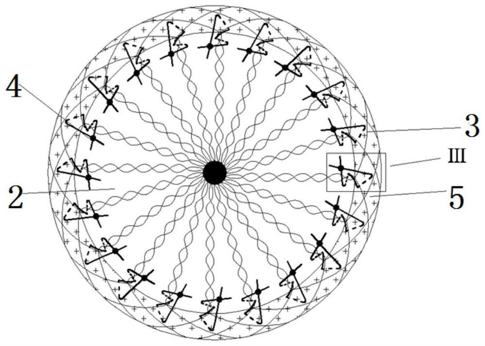
[0086] Such as Figure 1-3 As shown, this embodiment provides a new membrane-coated occlusion disc, which includes a plurality of elastic and / or shape-memory support rods, a first choke film, and a first deformation compensation structure 4; wherein, a plurality of support rods From the first central part 6, the first support expansion surface 1, the waist support expansion surface 3 and the second support expansion surface 2 are sequentially extended, and they are gathered at the second central part 7 to form a cage-like structure; Coating film 5, coating film 5 is wrapped on the outer surface of the first central part 6, the inner and outer surfaces of the first support unfolding surface 1 and the outer surface of waist support unfolding surface 3, the far-end edge of coating film 5 and the second The support deployment surface 2 is connected by a first deformation compensation structure 4 .

[0087] In the prior art, the flow-blocking membrane on the occlusion disk is plug...

Embodiment 2

[0093] Such as Figure 10-12 Among them, compared with embodiment 1, the first difference between embodiment 2 and embodiment 1 is that: the first choke membrane also includes a reinforced blocking body 9, which is arranged on the second support expansion surface of the blocking disk 2, the edge of the reinforced blocking body 9 is connected with the edge of the coating film 5 and the lumbar support unfolding surface 3 through the first deformation compensation structure 4, so that in the natural state, the coating film 5 and the reinforced blocking body 9 form a The closed cage shape adapted to the shape of the occlusion disk, the reinforced occlusion body 9 is made of a flexible film, and the flexible film has a microporous structure 51, which is convenient for liquid to enter and exit. In addition, the microporous structure 51 is more conducive to tissue growth, so the reinforced occlusion body 9 provided by the occlusion disk is also conducive to accelerating the endotheli...

Embodiment 3

[0101] refer to Figure 14 , 15 , The first difference between embodiment 3 and embodiment 1 is: the coating film 5 not only covers the lumbar support deployment surface 3 but also covers the second support deployment surface 2, and the coating film at the second support deployment surface 2 5 is provided with a microporous structure 51, so that liquid can come in and go out, which is convenient for emptying before operation.

[0102] The second difference is that: if Figure 15 Among them, the first deformation compensation structure 4 is located at the edge of the coating film 5, and the first deformation compensation structure 4 is a series line on a plurality of independent support rods surrounding the second support development surface 2, and the series line passes through or A plurality of independent support rods and a covering film 5 on the second support deployment surface 2 are wound, so that the series lines are connected end to end. The advantage of this design ...


PUM


Abstract

The invention discloses a novel film-coated plugging disc. The novel film-coated plugging disc comprises a plurality of supporting rods with elasticity and / or shape memory, a first flow blocking filmand a first deformation compensation structure, wherein the plurality of supporting rods sequentially extend out of a first support unfolding face and a second support unfolding face from a first central part to form a cage-shaped structure or bowl-shaped structure, the first flow blocking film comprises a coating film, the coating film at least coats inner and outer surfaces of the first supportunfolding face, and the local outer ring face of a connecting area of the first support unfolding face and the second support unfolding face, and the far-end edge of the coating film is connected withthe second support unfolding face through the first deformation compensation structure. By adopting a novel film coating method, the three-dimensional plugging is realized, a series of problems thatin the prior art, plugging is incomplete, residual shunting is easy to happen, and the like are solved, and the endothelialization is accelerated, so that the safety of the plugging disc is further improved.

Description

technical field [0001] The invention relates to the field of medical devices, in particular to a novel membrane-covered occlusion disc. Background technique [0002] Atrial fibrillation is one of the most common cardiac arrhythmia conditions and is the leading cause of hospital visits and hospitalizations for arrhythmia-related conditions, which is associated with decreased mobility, quality of life, cardiac function, and overall survival. As the population grows older, the social and economic burdens brought by atrial fibrillation will continue to increase. Although atrial fibrillation itself is not a fatal arrhythmia, it will cause stroke due to slow blood flow in the atrium and loss of atrioventricular synchronization. , heart failure and other complications increase the incidence rate, and even increase the mortality rate. [0003] Atrial fibrillation loses the effective contraction of the atrium, causing blood to stay in the left atrial appendage. In addition, the uniq...

Claims


Application Information

Patent Timeline
IPC IPC(8): A61B17/12
CPCA61B17/12031A61B17/12122A61B17/12159A61B17/12168A61B17/12172A61B2017/12054
Inventor 李彪张丽红李刚邵烨
Owner NINGBO DIOCHANGE MEDICAL TECH CO LTD
Features
  • Generate Ideas
  • Intellectual Property
  • Life Sciences
  • Materials
  • Tech Scout
  • Unparalleled Data Quality
  • Higher Quality Content
  • 60% Fewer Hallucinations
Learn More