
Novel high-reliability IGBT and manufacturing method thereof

A manufacturing method and reliability technology, applied in the new high-reliability IGBT and its manufacturing field, can solve the problems affecting the long-term reliability of the device, high doping concentration, etc., so as to improve the long-term reliability, reduce the impact, and improve the oxide layer. The effect of thickness

Inactive Publication Date: 2020-12-18
JIANGSU HAIDONG SEMICON TECH CO LTD
View PDF5 Cites 1 Cited by
  • Summary
  • Abstract
  • Description
  • Claims
  • Application Information

AI Technical Summary

Problems solved by technology

[0004] Therefore, the technical problem to be solved by the present invention is to overcome the high doping concentration in the Dummy Cell region in the prior art, which affects the long-term reliability of the device, thereby providing a new high-reliability IGBT and its manufacturing method

Method used


Image

  • Novel high-reliability IGBT and manufacturing method thereof
  • Novel high-reliability IGBT and manufacturing method thereof
  • Novel high-reliability IGBT and manufacturing method thereof

Examples


specific Embodiment approach

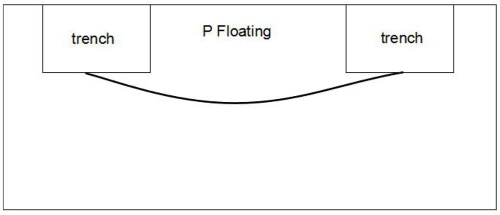
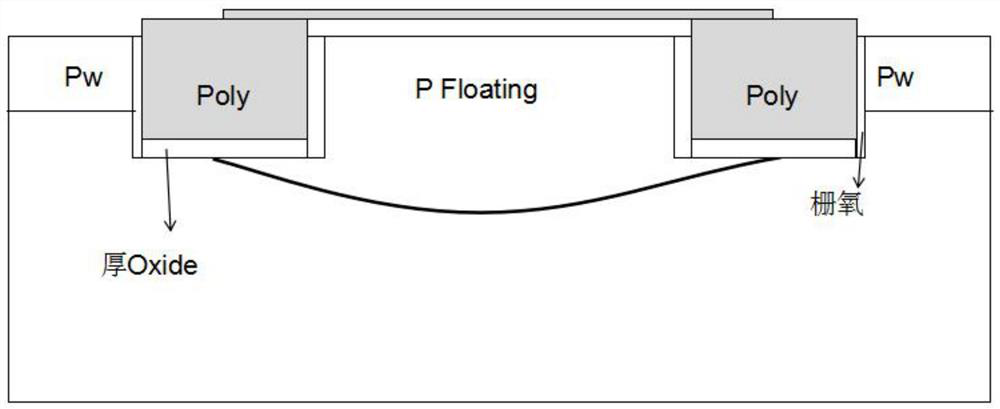
[0046] see figure 1 and figure 2 , a manufacturing method of a novel high-reliability IGBT, the following steps:

[0047] S1: Select a wafer substrate, open the area to be etched on the surface of the wafer substrate through a photolithography plate, and inject Boron ions, then form a dummy area through high temperature annealing, and deposit a certain thickness of oxide layer to cover the etching area.

[0048] Specifically, in one embodiment, the wafer substrate is an Fz wafer with a resistivity of 30Ω·cm. In other embodiments, the resistivity of the wafer substrate can also be 40Ω·cm, 50Ω·cm, 60Ω·cm, 70Ω·cm, 80Ω·cm, 90Ω·cm, 100Ω·cm, 110Ω·cm, Any value in 120Ω·cm.

[0049] The method of opening the area to be etched on the surface of the wafer substrate includes using a Terminal Ring photolithography plate to open by means of gluing, exposure, and development.

[0050] In the above steps, the dose of Boron ion implantation ranges from 1e12 to 1e13, and the implantation...


PUM

PropertyMeasurementUnit
electrical resistivityaaaaaaaaaa

Abstract

The invention relates to the technical field of power devices, in particular to a novel high-reliability IGBT and a manufacturing method thereof, which aim to solve the problem that the long-term reliability of a device is influenced due to the fact that a Dummy Cell region has very high doping concentration in the prior art. The manufacturing method is characterized by comprising the following steps of S1, opening a region needing to be etched on the surface of a wafer substrate through a photomask, injecting Boron ions, forming a Dummy region through high-temperature annealing, and depositing an oxide layer on the surface of the wafer to cover the etching region, S2, opening a region to be etched by using an Active photomask, and removing the surface oxide layer to open a Cell region, and S3, forming an etching masking layer on the surface of the wafer substrate, opening a region to be etched by using a Trench photomask, opening a deep groove etching window, and performing Si etchingto form a deep groove structure. By optimizing the trench gate structure, the thickness of the Dummy Cell side oxide layer is enhanced and the upper insulating dielectric layer is protected, the influence of the device on the injection of the oxide layer for a long time is reduced, and the long-term reliability is improved.

Description

technical field [0001] The invention relates to the technical field of power devices, in particular to a novel high-reliability IGBT and a manufacturing method thereof. Background technique [0002] IGBT (Insulated Gate Bipolar Transistor), Insulated Gate Bipolar Transistor, is a composite fully-controlled voltage-driven power semiconductor device composed of BJT (Bipolar Transistor) and MOS (Insulated Gate Field Effect Transistor), with MOSFET The advantages of high input impedance and low conduction voltage drop of GTR. The saturation voltage of GTR is low, the carrying current density is large, but the driving current is large; the driving power of MOSFET is small, the switching speed is fast, but the conduction voltage drop is large, and the current carrying density is small. The IGBT combines the advantages of the above two devices, with low driving power and low saturation voltage. It is very suitable for the conversion system with a DC voltage of 600V and above, suc...

Claims


Application Information

Patent Timeline
Patent Type & Authority Applications(China)
IPC IPC(8): H01L21/331H01L29/739H01L29/423
CPCH01L29/4236H01L29/66348H01L29/7397
Inventor 赵家宽黄传伟李健吕文生谈益民
Owner JIANGSU HAIDONG SEMICON TECH CO LTD
Learn More