Novel compressed hydrogen filling machine for car

A technology for compressing hydrogen and refueling machines, which is applied in motor vehicles, road vehicles, mechanical equipment, etc. It can solve problems such as hidden dangers, rising temperature, and monotonous operation interface, so as to reduce construction costs, reduce floor space, and prevent flow rate. too fast effect

Pending Publication Date: 2020-12-25
河南豫氢装备有限公司
View PDF0 Cites 1 Cited by
  • Summary
  • Abstract
  • Description
  • Claims
  • Application Information

AI Technical Summary

Problems solved by technology

The most important problem is that during the filling process of hydrogen fuel electric vehicles, the temperature in the hydrogen storage tank in the vehicle will rise rapidly, which will bring huge safety hazards. This is because the flow rate of hydrogen gas is too high and Continuous heat release, so solving the temperature rise problem in this process is the premise of ensuring safe filling
[0005] In order to solve the problem of temperature rise, most of the current compressed hydrogen refilling machines for automobiles are equipped with a sequence control panel at the front end of the equipment to realize the switching of high, medium and low flow rates in the refilling machine, but it increases the overall hydrogen refueling station. cost
[0006] In addition, the compressed hydrogen refueling machine for automobiles also has problems such as the monotonous operation interface, which makes the hydrogen refueling operator feel very boring during the entire hydrogen refueling process, and does not have IC card payment and other functions and cannot realize hydrogen refueling. Hydrogen sampling analysis and many other issues

Method used


Image

  • Novel compressed hydrogen filling machine for car

Examples


Embodiment Construction

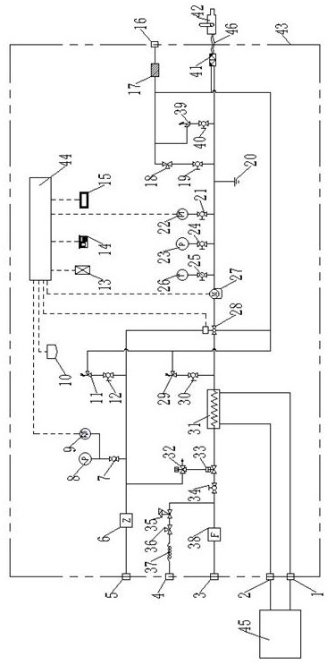
[0022] Describe technical scheme of the present invention in detail in conjunction with accompanying drawing, as figure 1 As shown, a novel compressed hydrogen refueling machine for automobiles comprises a casing 43, a PLC control system 44 arranged on the casing 43, a quick-loading chuck connector I1, a quick-loading chuck connector II2, and a hydrogen input interface 3. Hydrogen gas sampling port 4, drive gas input port 5, gas vent port 16, hydrogenation gun pipe telescopic port and the piping system set in the box 43, hydrogen gas input port 3 is sequentially connected with the filter 38 through the hydrogenation pipeline , high-pressure ball valve III 34, pneumatic ball valve 33, electronic pressure regulating valve 28, mass flow meter 27 and pull-off device 41 are connected, and the pull-off device 41 is connected with hydrogenation gun 42 through connecting hose II 46, and pneumatic ball valve 33 is connected with electronic The partial hydrogenation pipeline between the...


PUM


Abstract

The invention discloses a novel compressed hydrogen filling machine for a car. The machine comprises a box body, a PLC control system, a quick-assembled chuck joint I, a quick-assembled chuck joint II, a hydrogen input connector, a hydrogen sampling opening, a driving gas input connector, a gas emptying connector, a connecting hose and a pipeline system arranged in the box body, wherein the PLC control system, the quick-assembled chuck joint I, the quick-assembled chuck joint II, the hydrogen input connector, the hydrogen sampling opening, the driving gas input connector, the gas emptying connector and the connecting hose are arranged on the box body. The situation that under the circumstance of extreme high temperature, in the filling process of hydrogen, the temperature in a hydrogen storage tank of the car rises too fast, and it is ensured that the compressed hydrogen filling machine for the car can fill the hydrogen rapidly, efficiently and safely. A rapid pre-cooling system is arranged, and by means of the rapid pre-cooling system, hydrogen can be cooled to a preset target value in advance. An electronic pressure adjusting valve is further arranged, thus the filled hydrogen can be automatically adjusted to the needed flow range, and it is ensured that the hydrogen is filled into a vehicle-mounted hydrogen bottle of the hydrogen fuel electric car stably and efficiently.

Description

technical field [0001] The invention belongs to the technical field of hydrogen filling devices for hydrogen filling stations, and in particular relates to a novel compressed hydrogen filling machine for automobiles. Background technique [0002] As a clean, efficient, safe and sustainable new energy, hydrogen energy is regarded as the clean energy with the most development potential in the 21st century, and it is the strategic energy development direction of mankind. In recent years, the hydrogen energy industry has developed rapidly, and the country has formulated a long-term hydrogen energy development strategy from the perspective of sustainable development and safety strategies. [0003] As a transfer station between hydrogen fuel electric vehicles and hydrogen production plants, hydrogen refueling stations play a vital role in the development of the hydrogen energy industry. At the same time, the compressed hydrogen refueling machine for automobiles is the key equipme...

Claims


Application Information

Patent Timeline
Patent Type & Authority Applications(China)
IPC IPC(8): F17C5/06F17C13/04F17C13/02F17D5/00F17D5/02F17D3/01
CPCF17C5/06F17C13/02F17C13/023F17C13/025F17C13/026F17C13/04F17C2205/0352F17C2205/0388F17C2221/012F17C2227/0337F17C2250/032F17C2260/038F17C2260/042F17C2265/012F17C2270/0178F17C2270/0184F17D3/01F17D5/005F17D5/02Y02E60/32
Inventor 张家朋张攀周军张晨阳张晨
Owner 河南豫氢装备有限公司
Why Eureka
Try Eureka