Eureka AIR delivers breakthrough ideas for toughest innovation challenges, trusted by R&D personnel around the world.

High-sensitivity optical fiber photoacoustic gas detection system and method

A photoacoustic gas and high-sensitivity technology, which is applied in the direction of using sound waves/ultrasonic waves/infrasonic waves to analyze fluids, measuring devices, and processing detection response signals. It can solve problems such as small gas production volume, sensitivity, and difficulty in improving signal-to-noise ratios Avoid poor stability, reduce the volume of the air chamber, and increase the effect of heat conduction

Active Publication Date: 2021-01-01
DALIAN UNIV OF TECH
View PDF15 Cites 1 Cited by
  • Summary
  • Abstract
  • Description
  • Claims
  • Application Information

AI Technical Summary

Problems solved by technology

[0004] The purpose of the present invention is to propose a high-sensitivity fiber optic photoacoustic gas detection system and method, aiming to solve the difficult problem of improving the sensitivity and signal-to-noise ratio of the system based on the diaphragm acoustic transducer in the current fiber optic photoacoustic spectrum gas detection scheme , and the system has a small gas production rate, which provides a new idea for the application of optical fiber photoacoustic gas detection technology

Method used


Image

  • High-sensitivity optical fiber photoacoustic gas detection system and method
  • High-sensitivity optical fiber photoacoustic gas detection system and method
  • High-sensitivity optical fiber photoacoustic gas detection system and method

Examples


Embodiment Construction

[0030] The specific embodiments of the present invention will be described in detail below in conjunction with the technical solutions and accompanying drawings.

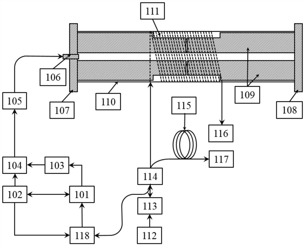
[0031] A fiber optic photoacoustic gas sensing system based on a hollow elastic tube, including a computer 101, a signal processing circuit 102, a digital signal generator 103, an adder 104, a DFB laser 105, an optical fiber collimator 106, and a 1# plane mirror 107, 2# plane mirror 108, photoacoustic cavity 109, hollow elastic tube 110, single-mode sensing fiber 111, ASE light source 112, fiber isolator 113, 2×2 fiber coupler 114, reference fiber 115, 1# Faraday Rotating mirror 116, 2# Faraday rotating mirror 117, spectrometer 118. The computer 101 controls the signal processing circuit 102 to output a sinusoidal modulation signal, and at the same time controls the digital signal generator 103 to output a sawtooth wave signal. After the two signals pass through the adder 104, the DFB laser and its driving circuit 1...


PUM

PropertyMeasurementUnit
Thicknessaaaaaaaaaa
Radiusaaaaaaaaaa
Young's modulusaaaaaaaaaa

Abstract

The invention belongs to the technical field of optical fiber gas detection, and provides a high-sensitivity optical fiber photoacoustic gas detection system and method. An optical fiber acoustic wavesensing unit of a Michelson interference structure is adopted, a hollow elastic tube serves as an acoustic transducer, a section of copper tube with the same length as the elastic tube is placed in the elastic tube, and a copper tube cavity serves as a photoacoustic cavity, so that the integration of photoacoustic signal excitation and detection is achieved, and photoacoustic signals are subjected to data processing to obtain the gas concentration. According to the invention, the hollow elastic tube is used as the acoustic transducer, so that the defects of noise sensitivity and poor stability caused by a film acoustic transducer are avoided; and the copper tube as long as the elastic tube is arranged in the elastic tube , so that the resonant frequency of the acoustic wave sensor is close to that of a photoacoustic cell, and the sensitivity and signal-to-noise ratio of photoacoustic signal detection can be remarkably improved. In addition, the copper tube photoacoustic cavity is usedto reduce the volume of an air chamber and promote the heat exchange. The detection system has the advantages of high sensitivity, high signal-to-noise ratio and good stability, and provides a competitive technical scheme for optical fiber photoacoustic gas detection.

Description

technical field [0001] The invention belongs to the technical field of optical fiber gas detection, and relates to a high-sensitivity optical fiber photoacoustic gas detection system and method. Background technique [0002] Optical fiber photoacoustic trace gas detection technology has the advantages of anti-electromagnetic interference, intrinsic safety, high sensitivity and fast response speed, so it occupies an increasing proportion in the field of trace gas detection. It plays an important role in the fields of dissolved gas analysis in transformer oil, gas monitoring in coal mines, and safety monitoring in petrochemical plants. [0003] Laser photoacoustic spectroscopy is a typical technique in indirect absorption spectroscopy. The output of the laser is modulated with a sine wave of frequency f, and a sawtooth wave is used to steer the laser so that its output light scans the absorption lines of the gas. Gas molecules are excited to high energy levels by absorbing l...

Claims


Application Information

Patent Timeline
IPC IPC(8): G01N21/17G01N21/3504G01N29/02G01N29/46
CPCG01N21/1702G01N21/3504G01N29/02G01N29/46G01N2021/1704G01N2291/021
Inventor 陈珂张博郭珉李晨阳安冉李辰溪宫振峰
Owner DALIAN UNIV OF TECH
Why Eureka
Eureka Blog
Learn More